PART3AC Circuit
Experiment 2 :Inductive Circuit
Theory
When the sine wave current expressed as i=Im sinωt flows on the ideal condenser which has inductance L, the voltage drop υ toward the current direction can be expressed as below
Here, the relationship between the maximum value of voltage and current is Vm=ωLIm, and the effective value is V=ωLI or I=V/(ωL). Fig. 3-6 shows the relationship between the voltage and the current in the inductance circuit. Therefore, in the AC circuit having inductance only, the voltage and the current are the sine wave of same frequency and the phase of the voltage is 90° faster than that of the current. The ratio of effective values(or maximum values) of the voltage and the current is XL=ωL. Inductor is a kind of AC resistance. XL is called inductive reactance and defined as below.
![X_L=ΩL=2πfL [Ω]](../image/part3/formal3.8.gif)
Here, f is the AC frequency (unit: Hz) and L is the inductance of coil(unit: Henry). The unit of XL is Ω, which is same as that of the resistance.
Just as the resistance, the inductor increases as much as the number of connections when in series connection, and decreases when in parallel. (a) and (b) of Fig. 3-7 shows the circuits of inductor in series and in parallel connection, and the formula to calculate the combined inductance for each case is as below.
Combined Inductance for Series Connection
Combined Inductance for Parallel Connection
Experiment Process
tab1
Experiment 3-2.1 In Circuit-2 of M-03, compose a circuit as in Fig. 3-8, Fig. 3-9
Series Circuit
1.Connection(Circuit-2 of M-01)
1.Circuit Connection
In Circuit-2, connect between 2b terminal and 2c terminal, between 2c terminal and 2d terminal with yellow lines.
Connect the red lead line of digital LCR Meter to 2a terminal of Circuit-2.
Connect the black lead line of digital LCR Meter to 2d terminal of Circuit-2
2.Measurement
- 1When you choose the measurement range of digital LCR Meter as L measurement, the measured value is indicated. Record it in table 3-2. (Fig. 3-8(a))
- 2As in Fig. 3-8 (b), remove the line between 2b terminal and 2c terminal of Circuit-2 and record the measured value
- 3As in Fig. 3-8 (c), remove the line between 2c terminal and 2d terminal of Circuit-2 and record the measured value.
3.Calculation
1. Calculate the series combined inductance of L1+L2, L1+L2+L3 and record it in table3-2.
Parallel Circuit
1.Connection(Circuit-2 of M-03)
Circuit Connection
In Circuit-2, connect between 2e terminal and 2h terminal with yellow line. (Fig. 3-9(a))
Connect the red lead line of digital LCR Meter to 2e terminal of Circuit-2.
Connect the black lead line of digital LCR Meter to 2l terminal of Circuit-2.
2.Measurement
- 1Record measured value indicated on the window of digital LCR Meter in table 3-2.
- 2As in Fig. 3-9 (b), connect between 2f terminal and 2i terminal of Circuit-2 and record the measured value.
- 3As in Fig. 3-9 (c), connect between 1g terminal and 1j terminal of Circuit-2 and record the measured value.
3.Calculation
1.Calculate parallel combined inductance of L1+L2, L1+L2+L3 and record it in table 3-2.
In Case of No Digital LCR Meter(Reactance Meter)
[Parallel Combined Reactance Measurement] Using Indirect Measurement of Fig. 3-8(d)
1.Connection
1.Circuit Connection
Connect between 2e terminal and 2h terminal, between 2f terminal and 2l terminal, between 2g terminal and 2j terminal, and between 2k terminal and 2m terminal with yellow lines.
2.Measuring Instrument Connection
Function Generator Connection
Connect between A+ terminal of Signal Output on the front panel and 2f terminal of Circuit-2 with red line.
Connect between A- terminal of Signal Output on the front panel and 2n terminal of Circuit-2 with red line.
Voltmeter Connection
Connect between A+ terminal of Signal Output CH A on the front panel and 2h terminal of Circuit-2 with red line, and between A- terminal and 2k terminal of Circuit-2 with black line.
Connect between B+ terminal of Signal Output CH B on the front panel and 2m terminal of Circuit-2 with red line, and between B- terminal and 2n terminal of Circuit-2 with black line.
2.Wiring Diagram
flash
3.Measurement
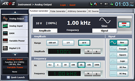
- 1Choose analog output at the left menu of front panel.
In Function Generator window, choose Amplitude as , Frequency as and Signal as , and click to output 1KHz 10V p-p
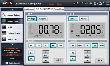
- 2Choose signal input at the left menu of front panel
Choose Volt & Ampere Meter and choose , , at CH A and CH B each, then the measured value is indicated
4.Calculation
1. Measure parallel combined inductance using the following formula and record it in table 3-2.
[Series Combined Inductance Measurement] Using Indirect Measurement of Fig. 3-8(d)
1.Connection
1.Circuit Connection
Connect between 2d terminal and 2m terminal with yellow line.
2.Measuring Instrument Connection
Function Generator Connection
Connect between A+ terminal of Signal Output on the front panel and 2a terminal of Circuit-2 with red line.
Connect between A- terminal of Signal Output on the front panel and 2n terminal of Circuit-2 with red line.
Voltmeter Connection
Connect between A+ terminal of Signal Output CH A on the front panel and 2a terminal of Circuit-2 with red line, and between A- terminal and 2d terminal of Circuit-2 with black line.
Connect between B+ terminal of Signal Output CH B on the front panel and 2m terminal of Circuit-2 with red line, and between B- terminal and 2n terminal of Circuit-2 with black line.
2.Wiring Diagram
flash
3.Measurement
Do as in [Parallel Combined Inductance Measurement].
4.Calculation
1. Calculate series combined inductance using the following formula and record it in table 3-2.