PART3AC Circuit
Experiment Purpose
- 1.Investigate how the value changes when connecting the capacitor and the inductor in series or in parallel.
- 2.In the AC circuit, an inductor which is called Choke or Coil and a capacitor which is called capacity or condenser are generally used. Learn the characteristics of the inductor and the capacitor in the AC circuit.
- 3.Investigate what characteristics the circuit, which is composed of the inductor and the capacitor which are in complementary relationship, has according to the frequency.
- 4.Compose a filter using the inductor and the capacitor and investigate the current change of each element according to the frequency.
Experiment 1 :Capacitive Circuit
Theory
When the sine wave current expressed as i=Im sinωt flows on the ideal condenser which has capacitance(C) only, the voltage drop υ toward the current direction can be expressed as below

Here, the relationship between the maximum value of voltage and current is Vm=(1/ωC)Im, and the effective value is V=(1/ωC)I or I=ωCV. Fig. 3-2 shows the phase relationship between the voltage and the current of the capacitive circuit. Therefore, in the AC circuit having capacitance only, the voltage and the current are the sine wave of same frequency and the phase of the voltage is 90° slower than that of the current. The ratio of effective values of the voltage and the current is Xc=1/(ωC). Also, Xc works as a sort of AC resistance which restricts the current of capacitive circuit so Xc is called capacitive reactance and defined as below.
![X_c=-1/(ωC)=-1/(2πfC) [ω]°)](../image/part3/formal3.2.gif)
Here, C is capacitance (unit: Farad), f is the AC frequency (unit: Hz) and, the unit of Xc is Ω, which is same as that of the resistance.
When in series connection, the capacity of the capacitor is smaller than the minimum capacity among the series connection, and when in parallel connection, it increases as the sum of capacities. (a) and (b) of Fig. 3-3 shows the circuits of capacitor in series and in parallel connection, and the formula to calculate the combined capacitance for each case is as below.
Combined Capacitance for Series Connection
Combined Capacitance for Parallel Connection
One noteworthy thing here is that the capacitor should be used within the working voltage, that is, the pressure-resistance of the capacitor. If the capacitors of same capacity and same pressure-resistance are connected in series, the pressure-resistance for both ends increases as much as the number of series connection. Fig. 3-3(c) shows that 3 30μF/10V capacitances are connected in series, the combined capacity becomes 10μF/30V.
Experiment Process
tab1
Experiment 3-1.1 In Circuit-1 of M-03, compose circuits as in Fig. 3-4 and Fig. 3-5
1.Connection(Circuit-1 of M-03)
Series Circuit
1.Circuit Connection
As in Fig. 3-4 (a), in Circuit-1, connect between 1b terminal and 1c terminal, between 1c terminal and 1d terminal with yellow lines.
In Circuit-1, connect between 1a terminal and High terminal of Multimeter on the front panel with red line.
In Circuit-1, connect between 1d terminal and Low terminal of Multimeter on the front panel with black line.
2.Wiring Diagram
flash
3.Measurement
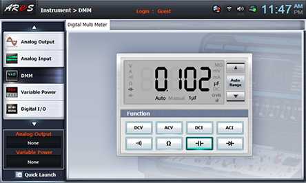
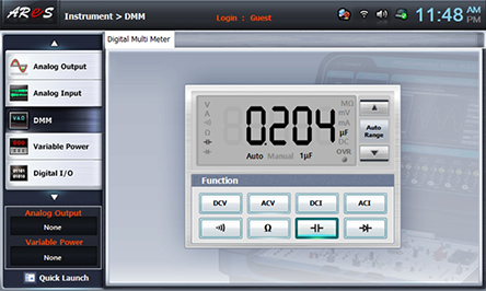
- 1Choose dmm at the left menu of Touch LCD panel.
- 2Click at Function of Digital Multi Meter window, than the measured value will appear on the window. Record it in table3-1.

- 3As in Fig. 3-4 (b), remove the connection line between 1b terminal and 1c terminal of Circuit-1 and record the measured value

- 4As in Fig. 3-4 (c), remove the connection line between 1c terminal and 1d terminal of Circuit-1 and record the measured value

4.Calculation
1. Calculate the series combined capacitance of C1+C2, C1+C2+C3 and record it in table 3-1.
Parallel Circuit
1.Connection
1.Circuit Connection
In Circuit-1, connect between 1e terminal and 1h terminal with yellow line. (Fig. 3-5 (a))
In Circuit-1, connect between 1e terminal and High terminal of Multimeter on the front panel with red line.
In Circuit-1, connect between 1l terminal and Low terminal of Multimeter on the front panel with black line
2.Wiring Diagram
flash
3.Measurement
- 1Record the measured value on Digital Multi Meter window in table 3-1.
- 2As in Fig. 3-5 (b), in Circuit-1, connect between 1f terminal and 1i terminal and record the measured value.
- 3As in Fig. 3-5 (c), in Circuit-1, connect between 1g terminal and 1j terminal and record the measured value.

4.Calculation
1. Calculate the parallel combined capacitance of C1+C2, C1+C2+C3 and record it in table 3-1.
In Case of No Digital LCR Meter(Capacitance Meter)
[Parallel Combined Capacitance Measurement] Using Indirect Measurement of Fig. 3-4(d)
1.ConnectionCircuit Connection
1.Circuit Connection
Connect between 1e terminal and 1h terminal, between 1f terminal and 1i terminal, between 1g terminal and 1j terminal, between 1k(or 1l) terminal and 1m terminal with yellow lines.
2.Measuring Instrument Connection
Function Generator Connection
Connect between A+ terminal of Signal Output on the front panel and 1f terminal of Circuit-1 with red line
Connect between A- terminal of Signal Output on the front panel and 1n terminal of Circuit-1 with red line.
Voltmeter Connection
Connect between A+ terminal of Signal Output CH A on the front panel and 1h terminal of Circuit-1 with red line, and between A- terminal and 1k(or 1l) terminal of Circuit-1 with black line.
Connect between B+ terminal of Signal Output CH B on the front panel and 1m(or 1k) terminal of Circuit-1 with red line, and between B- terminal and 1n terminal of Circuit-1 with black line.
2.Wiring Diagram
flash
3.Measurement
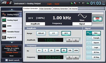
- 1Choose analog_output at the left menu of front panel.
In Function Generator window, choose Amplitude as , Frequency as and Signal as , and click output 1KHz 10Vrms
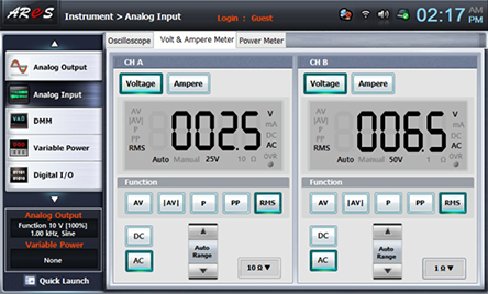
- 2Choose analog input at the left menu of front panel
Choose Volt & Ampere Meter and choose , , at CH A and CH B each, then the measured value is indicated. Record it in table 3-1.
4.Calculation
Calculate parallel combined capacitance with the formula below and record it in table 3-1.
[Series Combined Capacitance Measurement] Using Indirect Measurement of Fig. 3-4(d)
1.Connection
1.Circuit Connection
Connect between 1d terminal and 1m terminal with yellow line.
2.Measuring Instrument Connection
Function Generator Connection
Connect between A+ terminal of Signal Output on the front panel and 1a terminal of Circuit-1 with red line.
Connect between A- terminal of Signal Output on the front panel and 1n terminal of Circuit-1 with red line.
Voltmeter Connection
Connect between A+ terminal of Signal Output CH A on the front panel and 1a terminal of Circuit-1 with red line, and between A- terminal and 1d terminal of Circuit-1 with black line.
Connect between B+ terminal of Signal Output CH B on the front panel and 1m terminal of Circuit-1 with red line, and between B- terminal and 1n terminal of Circuit-1 with black line.
2.Wiring Diagram
flash
3.Measurement
Do as in [Parallel Combined Capacitance Measurement].
4.Calculation
1. Calculate series combined capacitance with the formula below and record it in table 3-1.