


PART1DC Circuit
Experiment 3 : Kirchhoff’s Law
Theory
Kirchhoff’s law explains the relationship between voltage and current in a complex circuit that has more than 2 voltage generators. It is classified as law of voltage and law of current
Kirchhoff’s Law of Voltage
In the circuit that has multiple voltage generator, if the closed circuit is composed for each voltage generator, the sum of voltage rise and voltage drop is same. That is, the sum of all voltages in the closed circuit is "0".
In Fig. 1-10(a), if the current flows clockwise, EB is voltage rise and ER1, ER2 are voltage drops.
Therefore, EB = ER1 + ER2 and EB – ER1 – ER2 = 0.
Kirchhoff’s Law of Current
In each node of parallel circuit, the sum of incoming current is same as that of outgoing current.
In Fig. 1-10(b), the incoming current to node A is IT, and the outgoing currents are IR1, IR2.
Therefore, IT = IR1 + IR2 and IT – IR1 – IR2 = 0.
Experiment Process
tab1
Experiment 1-3.1 Kirchhoff’s Law of Current (In Circuit-3 of M-01, compose a circuit as in Fig. 1-11.)
1.Connection(Circuit-3 of M-01)
1.Power Connection
fConnect between V1 terminal on the left Variable Power of M01 board and 3d(12V+)terminal of Circuit-3 with red line.
Connect between V2 terminal on the left Variable Power of M01 board and 3f(8V+)terminal of Circuit-3 with red line.
Connect between com terminal on the left Variable Power of M01 board and 3h(-) terminal of Circuit-3 with black line.
2.Measuring Instrument(Ammeter) Connection
I-1 Current Measurement
Connect between 3d terminal of Circuit-3 and mA/A terminal of Multimeter on the front panel with red line, and between 3a terminal and Low terminal with black line.
Connect between 3b terminal and 3e terminal and between 3c terminal and 3f terminal with yellow lines.
I-2 Current Measurement
Connect between 3f terminal of Circuit-3 and mA/A terminal of Multimeter on the front panel with red line, and between 3c terminal and Low terminal with black line.
Connect between 3a terminal and 3d terminal and between 3b terminal and 3e terminal with yellow lines.
I-3 Current Measurement
Connect between 3e terminal of Circuit-3 and mA/A terminal of Multimeter on the front panel with red line, and between 3b terminal and Low terminal with black line.
Connect between 3a terminal and 3d terminal and between 3c terminal and 3f terminal with yellow lines.
2.Wiring Diagram
I-1 Current Measurement
flash
I-2 Current Measurement
flash
I-3 Current Measurement
flash
3.Measurement
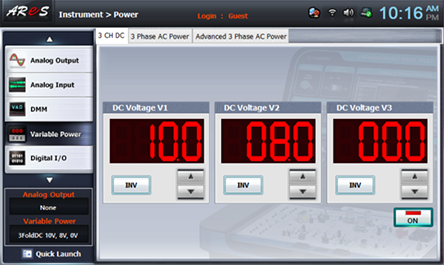
- 1Choose variable powerat the left menu of Touch LCD panel.
- 2Choose 3 CH DC tab and click at DC Voltage V1 to set up 10V, and click at DC Voltage V2 to set up 8V.
If you double-click DC Voltage V1 and click one, zero and ok using Quick Number Keypad, it can be input directly.
If you click , the output of DC 10V is input to V1, and the output of DC 8V to V2.
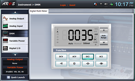
- 3Compose the connection as Measuring Instrument>Ammeter Connection>I-1 Current Measurement> and click dmmat the left menu, then Digital Multi Meter window appears. If you click , the current value and current direction of I-1 is measured. Record it in Fig. I-1 of table 1-3.
- 4Compose the connection as Measuring Instrument>Ammeter Connection>I-2 Current Measurement>and then the current value and current direction is measured in Digital Multi Meter window. Record it in Fig. I-2 of table 1-3.
- 5Compose the connection as Measuring Instrument>Ammeter Connection>I-3 Current Measurement>and then the current value and current direction is measured in Digital Multi Meter window. Record it in Fig. I-3 of table 1-3.
4.Calculation
1. Calculate the current value according to the formula and record it in the table.
Experiment 1-3.2 Kirchhoff’s Law of Voltage (In Circuit-3 of M-01, compose a circuit as in Fig. 1-11.)
1.Connection(Circuit-3 of M-01)
1.Circuit Connection
Connect between 3a terminal and 3d terminal, between 3b terminal and 3e terminal and between 3c and 3f terminal with yellow lines.
2.The Power Connection is same as Experiment 3-1
3.Measuring Instrument(Voltmeter) Connection
V-1 Connection
Connect between Signal Input A+ terminal on the front panel and 3a terminal of Circuit-3 with red line, and between A- terminal and 3b terminal with black line.
V-2 Connection
Connect between Signal Input B+ terminal on the front panel and 3c terminal of Circuit-3 with red line, and between B- terminal and 3b terminal with black line.
V-3 Connection
Connect between High terminal of Multimeter on the front panel and 3e terminal of Circuit-3 with red line, and between Low terminal and 3h terminal with black line.
2.Wiring Diagram
flash
3.Measurement
- 1Choose variable powerat the left menu of Touch LCD Panel, choose 3 CH DC tab and click at DC Voltage V1 to set up 10V, and click at DC Voltage V2 to set up 8V
If you click , the result is as below and the output of DC 10V from V1 and DC 8V from V2 are input to the circuit.
- 2Choose analog inputat the left menu of Touch LCD Panel, choose Volt & Ampere Meter tab and click , , for ChA and CH B each.
Record the measured values of CH A and CH B at V-1 and V-2 of table 1-4. Here, CH A is voltage V-1, and CH B is voltage V-2.
- 3If you click dmmat the left menu and click at Digital Multi Meter window, the voltage of V-3 is measured. Record it at V-3 of table 1-4.
4.Calculation
Calculate the value of voltage according to the formulae and record it in the table.
Here, ER1=I1∙R1, ER2=I2∙R2, ER3=I3∙R3 And R1,R2,R3,I1,I2,I3 are measured values (To measure R1,R2,R3, remove the power source, voltmeter and ammeter in the circuit and measure the both ends of each resistance with Ohm meter.)
Resistance Measurement
1. Measurement(Circuit-3 of M-01)
- 1) Choose dmm at the left menu of Touch LCD Panel and click at Digital Multi Meter window.
- 2) Connect between High terminal of Multimeter on the front panel and 3a terminal of Circuit-3 with red line, and between Low terminal and 3b terminal with black line. Record the measured value in R Value of Circuit of table 1-4.(R1 Measurement)
- 3) Remove two lines connected to 3a, 3b, connect those lines to 3b, 3c to measure R2, and remove the lines again and connect them to 3e, 3h to measure R3. Record the result in R Value of Circuit of table 1-4.