


PART8Operation Amplifier Circuit(OP AMP)
Experiment Purpose
- 1.Investigate characteristics of Inverting AMP.
- 2.Investigate characteristics of DC Offset through experiment.
- 3.Investigate characteristics of Non-Inverting AMP through experiment.
- 4.Investigate characteristics of Differential AMP through experiment.
- 5.Investigate characteristics of Summing AMP through experiment
Experiment 1 :Inverting Amplifier
Theory
Fig. 8-2 shows OP-Amp connected as inverting amplifier. This is because the input signal is applied to the inverting input(-) terminal through R1. R1 is called input factor and R2 feedback factor. The output voltage of the inverting amplifier can be expressed as below.
![V_O=-[R2/R1] V_i](../image/part8/formal8.1.gif)
In the formula above, the phase of output voltage is inverted to the input signal voltage. That is, there is phase difference of 180 degree. Closed loop gain(ACL) can be defined as below.
![A_L=A_OL/A_CL =A_OL [R1/R2]](../image/part8/formal8.2.gif)
As a result, the voltage gain of inverting amplifier can be less than, or more than, or same as 1.0. The size of gain is determined by resistance R1 and R2. The loop gain(AL) is as below.
![A_L=A_OL/A_CL =A_OL [R1/R2]](../image/part8/formal8.3.gif)
Here, AOL means open loop gain. The input impedance of inverting amplifier is simplified by input factor R1 and it can be much smaller than the input impedance of non-inverting amplifier circuit. The output impedance(Zo) of the circuit is determined by the output impedance of OP-Amp and loop gain. That is, it is as below.
![Z_O=Z_Oi/A_L =Z_Oi [R2/(A_OL R1)]](../image/part8/formal8.4.gif)
Here, ZOi : Output Impedance of OP-Amp determined in the specifications of manufacturer
When R1 and R2 are same, it becomes the inverting amplifier whose gain is 1.0 and this is used when the output signal and input signal are same and only the polarities should be inverted.
Close loop gain of basic inverting amplifier can be controlled by changing other feedback resistance as in fig. 8-3. Meanwhile, if analog switch(for example, 4016 CMOS) is used, the voltage gain of OP-Amp can be controlled digitally as in fig. 8-4.
The resistance of 4016 CMOS in ON state is normally 300Ω, so when controlling this switch, the calculation of voltage gain for each close loop can be designed by considering the resistance value of feedback resistance and 300Ω resistance in ON state. The analog switch can be controlled easily by digital circuit.
Experiment Process
tab1
Experiment 8-1.1 Inverting Amp Experiment (In Circuit-1 of M-08, compose an inverting AMP Circuit as in fig. 8-5.)
DC Inverting Amplification Experiment
1.Connection(Circuit-1 of M-08)
1.Power Connection
It is connected internally.
2.Measuring Instrument Connection
Function Generator Connection
Plug in BNC cable to BNC terminal of Signal Output on front panel and connect red line to 1a terminal of Circuit-1, and black line 1b terminal.
Voltmeter Connection
Connect between 1f terminal of Circuit-1 and High terminal of Multimeter on the front panel with red line, and between 1g terminal and Low terminal with black line.
2.Wiring Diagram
flash
3.Measurement
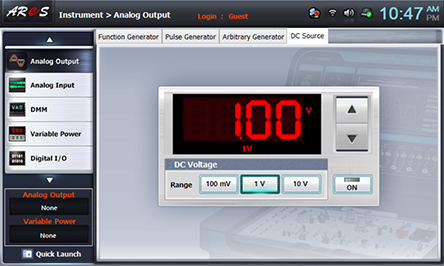
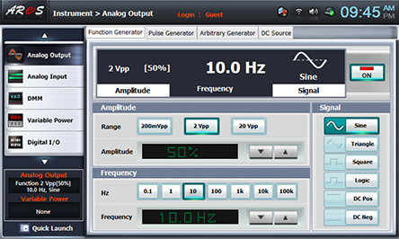
- 1Choose analog output at Touch LCD panel, click DC Source and set up DC Voltage as 1V.
- 2Offset Setup
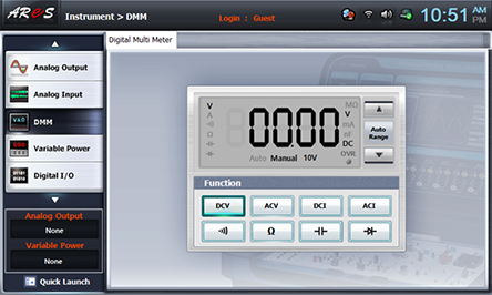
Choose dmm at the left menu of Touch LCD panel, and choose .
Set up R2 as maximum(Change all R2 setup SW as “H” status) and change R3 and adjust offset to make Output Vo of Circuit 1 as 0V.
When it becomes 0V, change all as “L” status.
- 3Measurement
Among R2 setup SW(8, 4, 2, 1), change SW 1 as “H” and make R2 value as 10kΩ.
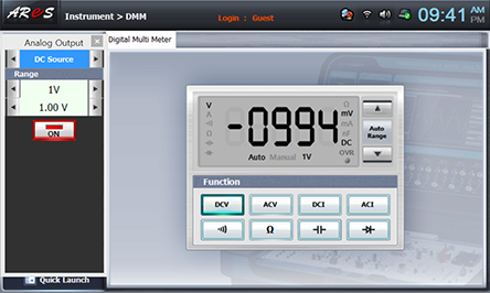
Choose quick launch at the left bottom of front panel, click analogOutput ,click at function to make DC Source appear and click to record the measured data of DMM in the relevant column of table 8-1.
Change R2 setup SW(8, 4, 2, 1) as table 8-1, measure the output voltage and record the result in table 8-1.
Resistance Value Setup using R2 Setup SW(8, 4, 2, 1)
Resistance Value Setup using R2 Setup SW(8, 4, 2, 1) R2[㏀] 10 20 30 40 50 60 70 80 90 100 SW
8421LLLH LLHL LLHH LHLL LHLH LHHL LHHH HLLL HLLH HLHL - 4Click of DC Source and cut off the input voltage.
4.Calculation
1. Using R2 value of table 8-1 and R1 resistance value of Circuit 1, calculate the output voltage with the formula below and record it.
![V_O=-[R_2/R_1 ] V_i](../image/part8/c1.gif)
2. Using the measured value in table 8-1, calculate the close loop gain(ACL) with the formula below and record it.
AC Inverting Amplification Experiment
1.Connection(Circuit-1 of M-08)
1.Power Connection
It is connected internally.
2.Measuring Instrument Connection
Function Generator Connection
Plug in BNC cable to BNC terminal of Signal Output on front panel and connect red line to 1a terminal of Circuit-1, and black line 1b terminal.
Voltmeter Connection
Connect between 1a terminal of Circuit-1 and A+ terminal of Signal Input CH A on the front panel of Multimeter with red line, and between 1b terminal and A- terminal with black line.
Connect between 1f terminal of Circuit-1 and B+ terminal of Signal Input CH B on the front panel of Multimeter with red line, and between 1g terminal and B- terminal with black line.
2.Wiring Diagram
flash
3.Measurement
- 1Change all R2 setup SW as "L" status.
Choose analog output at Touch LCD panel, click Function Generator and set up Amplitude Range as , Amplitude as amplitude 50%. Set up Signal as , and choose and set up Frequency as frequency 10hz.
Click and apply the output of Function Generator to input of Circuit-1.
- 2Measurement
Among R2 setup SW(8, 4, 2, 1), change SW 1 as “H” and make R2 value as 10kΩ.
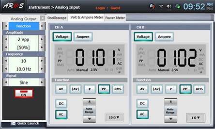
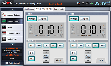
Choose analog input at front panel, choose Volt & Ampere Meter tab and click , , at CH A, CH B and record the measured value in the relevant column of table 8-2.
Measure the output voltage when R2 values are 10kΩ, 100kΩ and record the result in the relevant column and repeat the measurement according to the frequency given in table 8-2 and record the result..
4.Calculation
1. With the measured value of table 8-2, calculate the close loop gain(ACL) with the formula below and record it.