


PART3AC Circuit
EXperiment 3 :RC & RL Circuit
Theory
(1) The AC resistance of the capacitor is XC=-1/(2π fÇ) and XC gets lower as the frequency of AC flowing on the capacitor gets higher. All condensers of this feature has not only AC resistance but also DC resistance which delays the energy charge and resistance loss which discharges the charged energy. Therefore, if the AC resistance of the capacitor is XC and the DC resistance is R, the combined resistance is impedance and it is indicated as Z. The relationship between the current and the voltage follows Ohm’s law and the impedance Z and the phase are expressed as below.
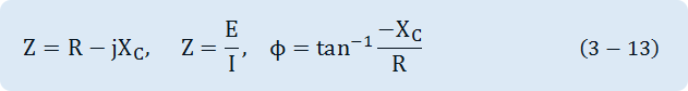
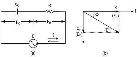
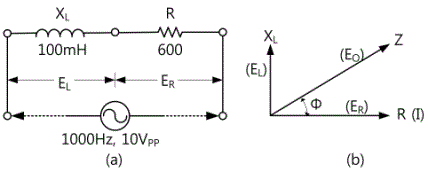
Fig. 3-10 shows R-C series circuit. The combined resistance (impedance) of R-C circuit becomes
Z=√(R2+XC2). And the phase difference of the voltage to the current becomes not 90° but as in Fig. 3-10 (b).
(2) The AC resistance XL of the inductor has 90° phase difference between the current and the voltage. However, if the DC resistance R is included in series in the coil, the combined resistance(impedance) can be expressed as the formula below and the relationship between the voltage and the current follows Ohm’s law.
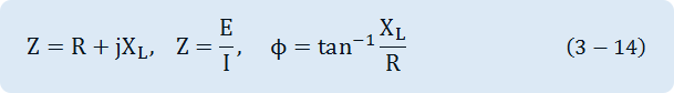
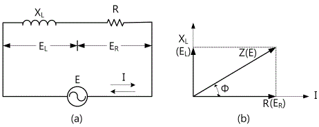
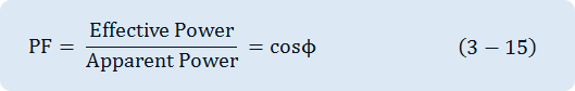
Fig. 3-11 shows R-L series circuit and the combined resistance(impedance) becomes Z=√(R2+XL2). And when DC resistance R exists in the circuit, the phase difference of the voltage to the current becomes not 90° but as in Fig. 3-11(b). In the circuit that has no AC resistance(Reactance), the calculation of the power load is P=IE. However AC circuit is different from the load that has DC resistance only because of the phase angle of the voltage and the current. The ratio of .impedance Z and R is called power factor and it is expressed as PF=R/Z=cosΦ. Here, the power to R load is called effective power and the power to Z is called apparent power, and they are expressed as below.
Experiment Process
RC Circuit
tab1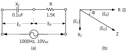
Experiment 3-3.1 RC Circuit (Compose as in Fig. 3-12 (a))
1.Connection
1.Circuit Connection
Function Generator Conenction
Connect between A+ terminal of Signal Output on the front panel and 3a terminal of Circuit-3 with red line, and between A- terminal and 3e terminal of Circuit-3 with black line.
Voltmeter Connection
Connect between A+ terminal of Signal Output CH A on the front panel and 3a terminal of Circuit-3 with red line, and between A- terminal and 3b terminal of Circuit-3 with black line.
Connect between B+ terminal of Signal Output CH B on the front panel and 3b terminal of Circuit-3 with red line, and between B- terminal and 3c terminal of Circuit-3 with black line.
2.Wiring Diagram
flash
3.Measurement
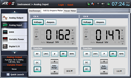
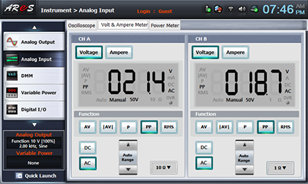
- 1Choose analog output at the left menu of front panel.
In Function Generator window, choose Amplitude as , Frequency as and Signal as , and click to output 1KHz 10V p-p.
- 2Choose analog input at the left menu of front panel.
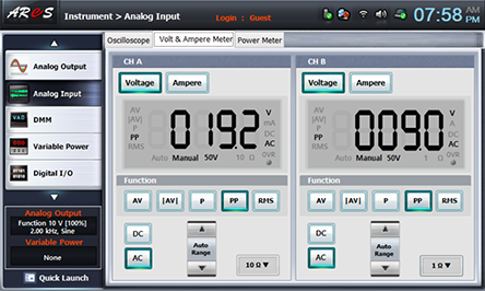
Choose Volt & Ampere Meter and choose , , at CH A and CH B each, then the measured value is indicated. Record it in the Relevant Frequency column. Ch A is Ec, and CH B is ER
- 3Choose analog output at the left menu of front panel.
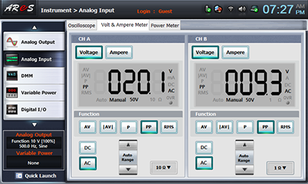
In Function Generator window, choose Amplitude as , Frequency as and click to make frequency 500hz and execute process 2).
In Function Generator window, Amplitude as , Frequency as and click to make 1500Hz frequency 1.5khz and execute process 2).
In Function Generator window, Amplitude as , Frequency as and click to make 2000Hz frequency 2.0khz and execute process 2).


- 4Connect the red line between A+ terminal of Signal Input CH A and 3a terminal of Circuit-3 to 3d terminal, and the black line between A- terminal and 3b terminal of Circuit-3 to 3e terminal.
- 5Choose analog input at the left menu of front panel and choose Volt & Ampere Meter, then the measured value of CH A is Eo. Record it in table 3-3.
4.Calculation
1. Calculate impedance Z with the given formula and record it in table 3-3
RL Circuit
Experiment 3-3.2 RL Circuit (Compose as Fig. 3-13 (a))
1.Connection
1.Circuit Connect
Function Generator Connection
Connect between A+ terminal of Signal Output on the front panel and 3i terminal of Circuit-3 with red line, and between A- terminal and 3j terminal of Circuit-3 with black line.
Voltmeter Connection
Connect between A+ terminal of Signal Output CH A on the front panel and 3f terminal of Circuit-3 with red line, and between A- terminal and 3g terminal of Circuit-3 with black line.
Connect between B+ terminal of Signal Output CH B on the front panel and 3g terminal of Circuit-3 with red line, and between B- terminal and 3h terminal of Circuit-3 with black line.
2.Wiring Diagram
flash
3.Measurement
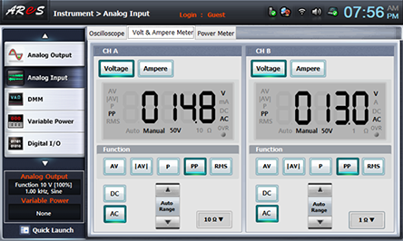
- 1Choose analog input at the left menu of front panel.
In Function Generator window, choose Amplitude as , Frequency as and Signal as , and click to output 1KHz 10V p-p.
- 2Choose analog inputat the left menu of front panel
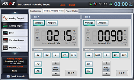
Choose Volt & Ampere Meter and choose , , at CH A and CH B each, then the measured value is indicated. Record it in the relevant Frequency column of table 3-4. Ch A is EL, and CH B is EC
- 3Choose analog output at the left menu of front panel
In Function Generator window, choose Amplitude as , Frequency as and click to make frequency 500hz and execute process 2).
In Function Generator window, choose Amplitude as , Frequency as and click to make frequency 1.5khz and execute process 2).
In Function Generator window, choose Amplitude as , Frequency as and click to make frequency 2.0khz and execute process 2).

- 4Connect the red line between A+ terminal of Signal Input CH A and 3f terminal of Circuit-3 to 3i terminal, and the black line between A- terminal and 3g terminal of Circuit-3 to 3j terminal.
- 5Choose analog input at the left menu of front panel and choose Volt & Ampere Meter, then the measured value of CH A is Eo. Record it in table 3-3
4.Calculation
1. Calculate impedance Z with the given formula and record it in table 3-4.