PART2The principle of a ammeter, voltmeter, Ohm-Meter
Experiment 3 :Ohm-Meter and resistance measurement (OHM-METER)
Theory
The Ohm-Meter is composed of a Meter, Zero Ohm multiplier, Range sorting resistance and DC Source (Battery), etc. Normally, a Meter's sensitivity ranges from 50μA to 1mA(FS) and the internal resistance is approximately 100Ω ~ 1kΩ.
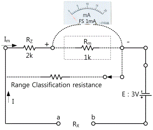
Concerning the remarkable difference of an Ohm-Meter from general voltmeters or ammeters, in the case of an ammeter or a voltmeter, 0V or 0A indicates the state of no current flowing a Meter, however, in the case of an Ohm-Meter, 0Ω indicates the state of current flowing a Meter FS. Namely, according to the principle of an Ohm-Meter, the resistance value is determined depending on how much the Meter is behind FS due to a certain measured resistance. Another characteristic of an Ohm-Meter is to require DC power that can release current to the measured resistor column from an Ohm-Meter. Accordingly, normal portable Ohm-Meters have an embedded battery. In the Fig. 2-8, assuming that the Meter's sensitivity is 1mA FS, the internal resistance is 1kΩ and the power supply of 3V is used, the Meter should indicate 1mA FS to make the Rx terminal become 0Ω(i.e. a, b is connected) so the resistance of overall circuit is as below.

Thus, the Meter's internal resistance Rm is 1kΩ so Rz = 3kΩ - 1kΩ. The Rz resistance is called the Ohm-Meter's Zero Ohm Multiplier. However, assuming that I is the current flowing through the circuit, Rx can be obtained by the below formula.

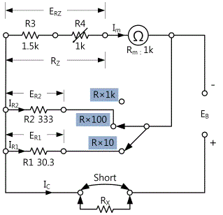
The actual circuit is often designed with minor changes such as Zero Adjusting circuit, etc. In common with an ammeter, an Ohm-Meter has the Range Shunt depending on the measuring range.
Experiment Process
tab1Experiment 2-3.1 Compose the circuit in the Circuit-4, 2 of M-02 as shown in the Fig. 2-9.
1.Wiring method(Circuit-4, 2 of M-02)
1.Power supply
Connect between Eb 3V Output terminal 4q of the Circuit-4 and DC 3V output terminal 2e(-) of the Circuit-2 with a black line.
Connect between Eb 3V Output terminal 4e of the Circuit-4 and DC 3V output terminal 2d(+) of the Circuit-2 with a red line
2.Connecting V, A, Ω indicator (In case of using an Analog meter)
Connect between Meter terminal 4o of the Circuit-4 and 2a (+) of the Circuit-2 with a red line.
Connect between Meter terminal 4p of the Circuit-4 and 2c of the Circuit-2 with a black line.
3.Connecting a voltmeter
Connect Eb 3V terminal 4e of the Circuit-4 and A+ terminal of the face panel Signal Input with a red line.
Connect Eb 3V terminal 4q of the Circuit-4 and A- terminal of the face panel Signal Input with a black line.
2.Wiring Diagram
RX1 wiring diagram
Wiring diagram of Zero ADJ
3.Measurement method
How to conduct Zero ADJ
Connect the terminal 4a and 4d with a yellow line and set the V, A, Ω indicator to 0(full scale) of a scale plate by turning a potentiometer of Zero Adj.
- 1In case of 0Ω (4a-4d short circuit), after setting as a full scale by varying Zero Adj, measure it.
- 2Measure the current flowing through the measured resistance(Rx1, Rx2) in the range of R×10(100mA).
After connecting terminal 4i and 4l of the Circuit-4 with a yellow line, conduct zero adjustment in accordance with <How to conduct Zero ADJ.>.
After connecting terminal 4d and 4b of the Circuit-4 with a blue line, record the current measured by the V, A, Ω indicator in the Table 2-5.(current flowing through Rx1)
After connecting terminal 4a and 4b of the Circuit-4 with a yellow line, connect terminal 4d and 4c with a blue line. Then, record the current measured by the V, A, Ω indicator in the Table 2-5(current flowing through Rx2).
- 3Measure the current flowing through the measured resistance(Rx1, Rx2) in the range of R×100(10mA).
After connecting terminal 4h and 4k of the Circuit-4 with a yellow line, conduct zero adjustment in accordance with <How to conduct Zero ADJ.>.
After connecting terminal 4d and 4b of the Circuit-4 with a blue line, record the current measured by the V, A, Ω indicator in the Table 2-5.(current flowing through Rx1).
After connecting terminal 4a and 4b of the Circuit-4 with a yellow line, connect terminal 4d and 4c with a blue line. Then, record the current measured by the V, A, Ω indicator in the Table 2-5(current flowing through Rx2).
- 4If you click dmm on the left menu of the Touch LCD panel, the Digital Multi Meter screen will pop up. At this time, click and measure the voltage of Eb 3V Output and record the value in the Table 2-5.
Experiment 2-3.2 Compose the circuit in the Circuit-4, 2 of M-02 as shown in the Fig.2-9.
1.Wiring method(Circuit-4, 2 of M-02)
1.Power supply
Connect Eb 3V Output terminal 4q of the Circuit-4 and com terminal of the Variable Power located on the left side of M02 with a black line
Connect Eb 3V Output terminal 4e of the Circuit-4 and V1 terminal of the Variable Power located on the left side of M02 with a red line.(Check the polarity carefully)
2.Connecting V, A, Ω indicator (In case of using an Analog meter)
Connect Meter terminal 4o of the Circuit-4 and 2a (+) of the Circuit-2 with a red line.
Connect Meter terminal 4p of the Circuit-4 and 2c of the Circuit-2 with a black line.
3.Connecting a voltmeter
Measuring ERz voltage
Connect terminal 4m of the Circuit-4 and High terminal of a face panel Multimeter with a red line.
Connect terminal 4n of the Circuit-4 and Low terminal of a face panel Multimeter with a black line.
Measuring ER1 voltage
Connect terminal 4f of the Circuit-4 and A+ terminal of the face panel Signal Input with a red line.
Connect terminal 4i of the Circuit-4 and A- terminal of the face panel Signal Input with a black line.
Measuring ER1 voltage
Connect terminal 4f of the Circuit-4 and A+ terminal of the face panel Signal Input with a red line.
Connect terminal 4h of the Circuit-4 and A- terminal of the face panel Signal Input with a black line.
2.Wiring Diagram
3.Measurement method
- 1In case of 0Ω(4a-4d short circuit), set as a full scale by adjusting VR through Zero Adj.
- 2Connect the terminal 4l and 4i with a yellow line and connect the terminal 4d and 4a with a red line(R×10).
- 3Select variable power on the left menu of the Touch LCD panel
- 4Select the 3 CH DC tab and click in the DC Voltage V1 to set 2.5V.
- 5Then, if you click , the output of DC 2.5V will be input to the circuit.
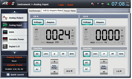
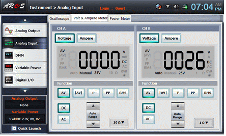
- 6After selecting analog input on the left menu, record the measured voltage of CH A(ER1), CH B(ER2) of a Volt & Ampere Meter in the Table 2-6.
After selecting the Volt & Ampere Meter tab on the main screen, click of CH A, CH B and click and in Function.
ER1
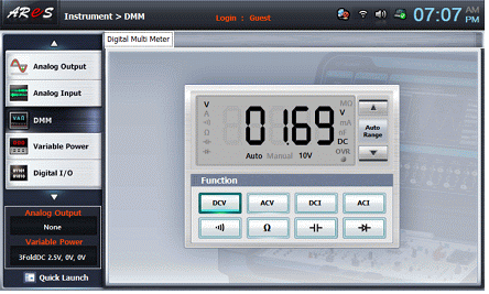
- 7If you click dmm on the left menu, the Digital Multi Mete screen will pop up. A this time, click to measure the voltage of ERz and record the result in the Table 2-6.
ERz
- 8Change the voltage into 3V and 3.5V at the stage of 4) and then, execute the stages of 6) and 7).
- 9After removing the terminal 4l and 4i connected in 2), connect the terminal 4 and 4h. Then, connect terminal 4d and 4a with a red line(R×100).
- 10Execute the stages of 3) ~8)
ER2
ERz
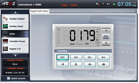
- 11Measuring Rz, R1, R2 resistance values
Remove all wiring
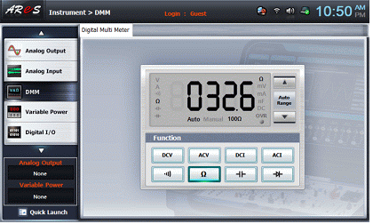
If you click dmm on the left menu, the Digital Multi Meter screen will pop up. At this time, click and connect the High terminal of a Multimeter and terminal 4m of the Circuit-4 with a red line. Then, after connecting the Low terminal and terminal 4p with a black line, record the measured resistance value of Rz in the Table 2-7.
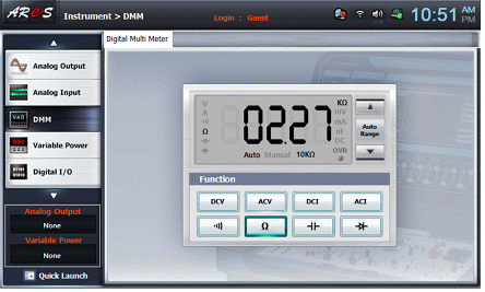
After connecting High terminal of a Multimeter and terminal 4m of the Circuit-4 with a red line, connect the Low terminal and terminal 4h with a black line. Then, record the measured resistance value of R2 in the Table 2-7.
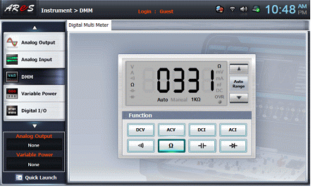
After connecting High terminal of a Multimeter and terminal 4m of the Circuit-4 with a red line, connect the Low terminal and terminal 4i with a black line. Then, record the measured resistance value of R1 in the Table 2-7.
4.Calculation
1. After calculating the measured values of the Table 2-5 and 2-6 with the formula provided in the Table 2-7, record the result.
Reference
1. Design formula (Rx : 0Ω) of R×10 (R1)


2. Design formula (Rx : 0Ω)of R×100 (R2)


3. Design formula of circuit current (Ic) when the measuring terminal is shorted at R×10

4. Design formula of circuit current (Ic) when the measuring terminal is shorted at R×100


