


PART4Transformer
Experiment Purpose
- 1.Investigate the generation principle of counter electromotive force by induction
- 2.Investigate the principles of transformer which is used to make the AC voltage up or down
- 3.In the transformer, investigate the change of inducted voltage according to the ratio of primary coil and secondary coil
- 4.Observe the change of current when there is load and when there is not on the transformer
- 5.Investigate the structure and function of autotransformer
Experiment 1 :Transformer Ratio
Theory
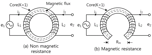
As in Fig. 4-2, the transformer is made by winding the rigid body which is called core with more than 2 coils which are insulated. Here, the coil which adds the current is called the primary coil and the coil on the opposite is called the secondary coil. There is no conductive connection between primary and secondary coil but if the current flows at the primary coil, the secondary current which is in proportion to the added current flows at the secondary coil so the voltage is generated. This is because of mutual induction active connecting between the primary and the secondary part, and this active is called Mutual Inductance. L1 is the inductance caused by the current i1 on the primary coil and L2 is the inductance generated at the secondary coil by the mutual induction active, and K is the coupling coefficient. Then, the mutual inductance can be defined as below.
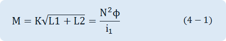
When there is no coupling loss, K=1, and i1 is the current of primary coil, N is the Turn number of secondary coil, φ is magnetic flux penetrating both coils. Generally, the coupling coefficient K has characteristics as below.
① K becomes bigger when two coils are located nearer. That is, if two coils are wound at one bobbin, the coupling coefficient becomes bigger than they are separately wound and become near.
② K increases when there is a core which generates the coil’s magnetic line of force as in Fig. 4-2.
If you know the mutual inductance of the transformer, you can get the voltage and the induced electromotive force (e2) as below.
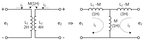


In the formula above, the value of e2 increases as M is bigger, the current of primary coil is bigger or the change time is shorter.
AC can transform the voltage easily by the transformer. On the other hand, DC should go through complicated process. The benefit of DC is that it can be charged. Here, AC means not only the power line AC of 50 cycle or 60 cycle but also the current that has frequency of general range including voice frequency or electric wave. To rise or drop this AC voltage, the material or production form of the transformer can vary according to the range of AC frequency. This can be classified as below.
- RF Transformer………………………………….used in scores kHz - hundreds MHz
- Pulse Transformer………………………………used in scores kHz - hundreds kHz
- AF Transformer………………………………… used in scores Hz - scores kHz
- Power Transformer …………………………….used in 50Hz - 60Hz
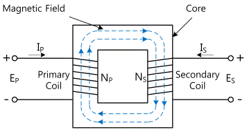
Here, AF transformer and power transformer used in scores Hz - scores kHz will be explained. Generally, the AF transformers use a core and as in Fig. 4-4, the core makes magnetic path for the magnetic line of force so that the magnetic line of force generated by the AC current of primary coil can generate AC current of same frequency to the secondary coil. According to the type of core, the efficiency and volume can be different.
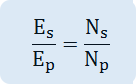
The formula below can be made between the primary and secondary coil of the transformer.
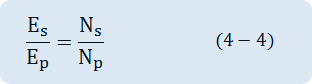
Here, Ep is the voltage added to the primary coil, Np is the number of turn wound on the primary coil, Es is the voltage generated at the secondary coil, and Ns is the number of turn wound on the secondary coil. If the output power of the secondary coil (Po) and the input power of the primary coil (Pi) are same, the efficiency of the transformer is 100% and the formula below can be made.
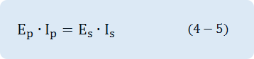
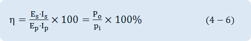
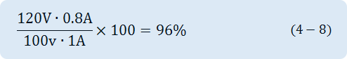
Here, the current flowing on the primary coil is Ip, and the current on the secondary coil is Is. The efficiency of actual transformer is usually 85-95% and it can be expressed as below.
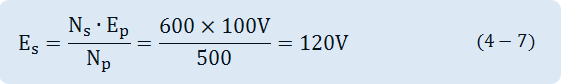
For example, if the turn number of the primary coil is 500, that of the secondary coil is 600 and the rated input voltage for the primary coil is 100V, then the secondary voltage Es is as below.
If the current flowing on the primary coil is 1A and that on the secondary coil is 0.8, the efficiency of this transformer is as below.
If the input voltage of the transformer is same, the turn number wound on the coil is in inverse proportion to the cross-section area of core and the frequency of input voltage, and in direct proportion to the output voltage. The turn number Np of the primary coil can be calculated as below.
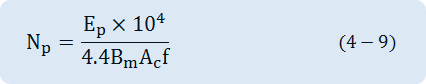
Here, Ep is the input voltage(V), Bm is the magnetic flux density(tesla), Ac is the crow-section area of the core(cm2 ), and f is the frequency of input voltage.
Experiment Process
tab1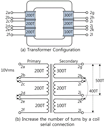
Experiment 4-1.1 In Circuit-1 of M-04, compose a circuit as in Fig. 4-4.
1.Connection(Circuit-1 of M-04)
Primary Coil Turn Number 600T, Secondary Coil Turn Number 300T, 200T, 100T Voltage Measurement
1.Circuit Connection
In Circuit-1, connect between 1b-1c terminals and 1d-1e terminals with yellow line
2.Power Connection
As in Fig. 4-4 (b), in Circuit-1, connect between terminal 1b and V1 terminal of Variable Power on the left with red line, and between 1f terminal and com terminal of Variable Power on the left with black line.
3.Measuring Instrument Connection
In Circuit-1, connect between 1k terminal and High terminal of Multimeter on the front panel with red line and between 1l terminal and Low terminal with black line.
In Circuit-1, connect between 1g terminal and A+ terminal of Signal Input CH A on the front panel with red line and between 1h terminal and A- terminal with black line.
In Circuit-1, connect between 1i terminal and B+ terminal of Signal Input CH B on the front panel with red line and between 1j terminal and B- terminal with black line.
2.Wiring Diagram
flash
3.Measurement
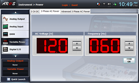
- 1Choose variable power at the left menu of Touch LCD panel and choose 3 Phase AC Power tab. Click to make 12.0V and click , then AC 12V will be output.
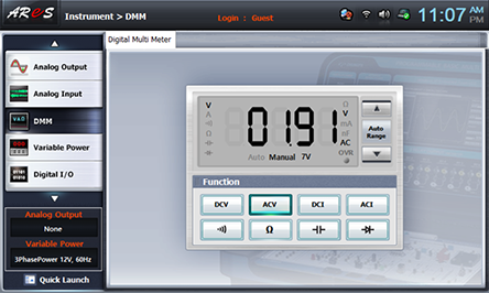
- 2Choose dmm at the left menu of Touch LCD panel.
If you click at Function of Digital Multi Meter window, the measured value of secondary coil 100T will be on the window. Record it in Primary Coil Turn Number 600t, Secondary Coil Turn Number 100T of table 4-1.
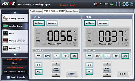
- 3Choose analog input at the left menu of Touch LCD panel.
If you choose Volt & Ampere Meter and choose , , at CH A and CH B each, the measured value is indicated. Record the value of CH A in Primary Coil Turn Number 600T, Secondary Coil Turn Number 300T column and the value of CH B in 200T column of table 4-1.
- 4<Primary Coil Turn Number 400T, Secondary Coil Turn Number 300T, 200T, 100T Voltage Measurement>
In Circuit-1, remove the yellow line between 1d-1e terminals and connect the line from com terminal of Variable Power on the left to 1f terminal to 1d terminal.
Execute Measurement 2)~3) and record the values in Primary Coil Turn Number 400T, Secondary Coil Turn Number 300T(CHA), 200T(CH B), 100T(DMM) columns of table 4-1.
- 5< Primary Coil Turn Number 200T, Secondary Coil Turn Number 100T, 200T, 300T Voltage Measurement >
In Circuit-1, remove the yellow line between 1b-1c terminals and connect the line from com terminal of Variable Power on the left to 1d terminal to 1b terminal
Execute Measurement 2)~3) and record the values in Primary Coil Turn Number 200T, Secondary Coil Turn Number 300T(CHA), 200T(CH B), 100T(DMM) columns of table 4-1.
- 6< Primary Coil Turn Number 200T, Secondary Coil Turn Number 400T, 500T, 600T Voltage Measurement >
- (1) Remove the connection line between terminals of the primary and the secondary coils, and connect between Variable Power V1 terminal and 1a terminal with red line, and between com terminal and 1b terminal with black line.
- (2) Secondary Coil Turn Number 400T Voltage Measurement
Connect between High terminal of Multimeter and 1g terminal of Circuit-1 with red line and connect Low terminal to 1l terminal. Connect between 1h terminal and 1k terminal with yellow line, and record the indicated value of DMM in Primary Coil Turn Number 200T, Secondary Coil Turn Number 400T columns of table 4-1. - (3) Second Coil Turn Number 500T Voltage Measurement
Connect between High terminal of Multimeter and 1g terminal of Circuit-1 with red line and connect Low terminal to 1j terminal. Connect between 1h terminal and 1i terminal with yellow line, and record the indicated value of DMM in Primary Coil Turn Number 200T, Secondary Coil Turn Number 500T columns of table 4-1. - (4) Second Coil Turn Number 600T Voltage Measurement
Connect between High terminal of Multimeter and 1g terminal of Circuit-1 with red line and connect Low terminal to 1l terminal. Connect between 1h-1i terminals and between 1j-1k terminals with yellow lines, and record the indicated value of DMM in Primary Coil Turn Number 200T, Secondary Coil Turn Number 600T columns of table 4-1.
- 7< Primary Coil Turn Number 400T, Secondary Coil Turn Number 400T, 500T, 600T Voltage Measurement >
- (1) Connect the line from com terminal of Variable Power to 1b terminal to 1d terminal, and connect between 1b-1c terminals of Circuit-1 with yellow line.
- (2) Execute (2), (3), (4) of process 6) and record the results in Primary Coil Turn Number 400T, Secondary Coil Turn Number 400T, 500T, 600T columns of table 4-1.
- 8< Primary Coil Turn Number 600T, Secondary Coil Turn Number 400T, 500T, 600T Voltage Measurement >
- (1) Connect the line from com terminal of Variable Power to 1d terminal to 1f terminal, and connect between 1b-1c terminals, and between 1d-1e terminals of Circuit-1 with yellow lines.
- (2) Execute (2), (3), (4) of process 6) and record the results in Primary Coil Turn Number 600T, Secondary Coil Turn Number 400T, 500T, 600T columns of table 4-1.
4.Calculation
1. The formula below can be made between the primary and the secondary coils of thetransformer.
Experiment Result Report
1. Experiment Result Table
2. Review and Explanation
1) When the Primary Coil Turn Number of table 4-1 is 400T, calculate the output voltage to the secondary coil turn number with the formula below and compare it with the measured result.