


Chapter 4AReS Real Time Measuring Software
4-5Digital Input/Output
Digital input/output is composed of individual settings for digital input/output and simultaneous setting for input/output and relay tab. Digital input/output is supported to maximum 16bit and the relay to 8.
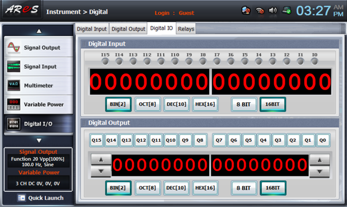
1.Digital Input
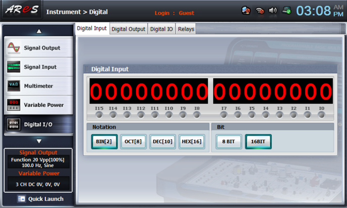
This displays digital input information on the screen. 4 kinds of base conversion are possible and up to 16bit can be displayed on the screen.
1. Digital Input Display Window
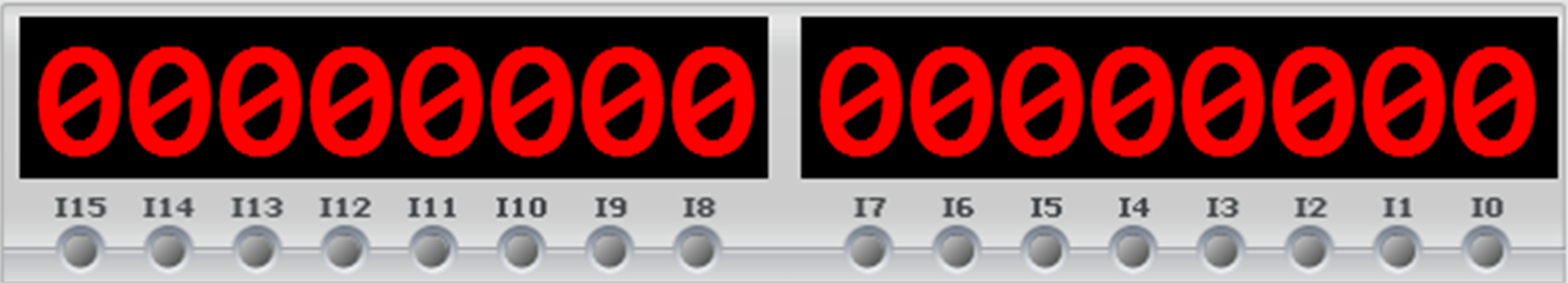
Here, the digital value is expressed in meter type according to the notation. At the LED lamp below, if the signal of relevant bit is 1(High level), the lamp is on and if it is 0(Low level), the lamp is off.
| Screen Area | Explanation |
|---|---|

|
Digital display window. 8 digits and on the screen according to the notation setting |
|
ON/OFF status display LED lamp per bit. If it is on, red LED is turned on. |
2. Notation
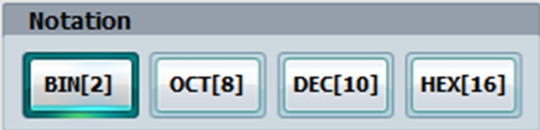
This is the notation setup button and the bit can be calculated by the chosen notation according to the input status.
| Screen Area | Explanation |
|---|---|
 |
Calculates the input 8/16 bit with binary number |
 |
Calculates the input 8/16 bit with octal number |
 |
Calculates the input 8/16 bit with decimal number |
 |
Calculates the input 8/16 bit with hexadecimal number |
* Binary(binary number), Octal or Octonary(octal number), Decimal(decimal number), Hexadecimal(hexadecimal number)
3. Bit
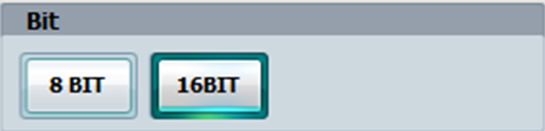
Here, the input information is expressed in 8 bit or 16 bit according to the bit choice.
| Screen Area | Explanation |
|---|---|
 |
Outputs the information by calculating with 8 bit. When the input bit information is over 8 bit, the calculation starts from the 8th bit as 0. ex> Express digital meter in 8 bit
|
 |
Outputs the information by calculating with 16 bit.
When the input bit information is over 8bit, the LED lamp on 8th bit is on, and the digital meter information is displayed on the right. ex> Express digital meter in 16 bit
|
* Note: Binary(binary number), Octal or Octonary(octal number), Decimal(decimal number), Hexadecimal(hexadecimal number)
2.Digital Output
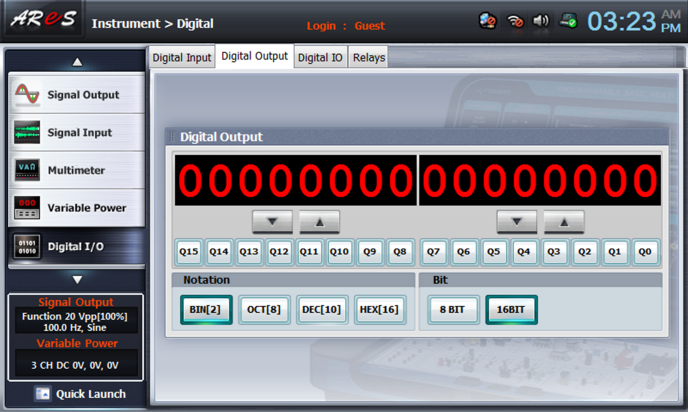
Here, digital output information is displayed on the screen, and 4 kinds of base conversion, that is, binary, octal, decimal, hexadecimal, are possible. 8 bit and 16 bit information can be displayed on the screen. The digital value on the screen is output as digital value at the digital output terminal of AReS trainer.
Digital output value is expressed as 1 or 0, and digital output voltage is output as +5V when 1(High level) and 0V when 0(Low level).
1. Digital Output Setting and Display Window

The digital value is expressed in meter type according to the notation. The button on the bottom means the digit of the bit and it is expressed as 1 when the button is on and as 0 when the button is off.
| Screen Area | Explanation |
|---|---|
 |
Digital display window. 8 digits and on the screen according to the notation setting |
| Bit button digit decrease/increase. Decreases and increases by 1 bit unit. (When it is pressed over 2 seconds, the increase and decrease is accelerated.) | |
 ~ ~  |
Toggle button for bit digit. When it is activated(ON), the relevant digit bit becomes 1 and is calculated according to the notation. |
2. Notation
This is the notation setup button and the bit can be calculated by the chosen notation according to the input status.
| Screen Area | Explanation |
|---|---|
|
Calculates the input 8/16 bit with binary number |
|
Calculates the input 8/16 bit with octal number |
|
Calculates the input 8/16 bit with decimal number |
|
Calculates the input 8/16 bit with hexadecimal number |
* Binary(binary number), Octal or Octonary(octal number), Decimal(decimal number), Hexadecimal(hexadecimal number)
3. Bit
Here, the input information is expressed in 8 bit or 16 bit according to the bit choice.
| Screen Area | Explanation |
|---|---|
|
Outputs the information by calculating with 8 bit. When the input bit information is over 8 bit, the calculation starts from the 8th bit as 0. ex> Express digital meter in 8 bit
|
|
Outputs the information by calculating with 16 bit. When the input bit information is over 8bit, the LED lamp on 8th bit is on, and the digital meter information is displayed on the right. ex> Express digital meter in 16 bit
|
* Note: Binary(binary number), Octal or Octonary(octal number), Decimal(decimal number), Hexadecimal(hexadecimal number)
3.Digital Input/Output
Here, digital input and output can be used in one program window, and by setting up input/output individually and connecting to external circuit, the input and output status can be monitored. The direction of this function is basically same as that of digital input and output.
1. Digital Input
Refer to 4-5-1 Digital Input.
2. Digital Output
Refer to 4-5-2 Digital Output.
4.Relays
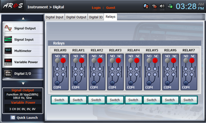
Total 8 relays can be controlled and they individually indicate NC(Normal Close), NO(Normal Open) status. By choosing switch key, current status can be inverted. The relay terminals of AReS provide COM, NC, NO terminal from RELAY0 to RELAY7. The relay is built in AReS so it can be used by connecting to the circuit.
The rating of relay built in AReS is as below.
| Type | DS1E-M-DC5V NASI | Note |
|---|---|---|
| Internal Control Power | 5V DC/ 400mW | Control/Control(coil) |
| Contact Material | Gold-clad sliver | Contact Rating (resistive) |
| Maximum Switching Power | 60W, 125 VA | |
| Maximum Switching Voltage | 220V DC, 250V AC | |
| Maximum Switching Current | 2A DC, AC | |
| Maximum Movement Current | 3A DC, AC |
Note: Initial contact resistance, max. 50mΩ (By voltage drop 6V DC 1A)
1. Relay Setting

There are total 8 relays from 0 to 7 and through the switch button, current status can be inverted and the relay contact can be controlled.
| Screen Area | Explanation |
|---|---|
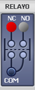 |
Relay status display window. Displays NC (Normal Close) / NO (Normal Open) status. In case of NC, the contact is on(COM and NC is connected) when the switch button is on, and in case of NO, the contact of COM and NO is connected when the switch button is on.. |
 |
Relay control(status inversion) switch. NC-> NO, NO-> NC |