


Chapter 4AReS Real Time Measuring Software
4-2Signal Input
Signal input is composed of taps for oscilloscope which changes the analog input source to digital and expresses as graph or number, voltmeter and ammeter, and wattmeter. It can receive two inputs, channel A and channel B.
1.Oscilloscope
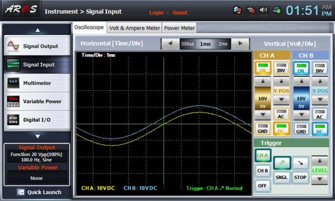
Oscilloscope can express the signal(voltage) value as the wave form graph by A(yellow), B(blue) channels according to the time setting, and it has signal(voltage) wave form display setting and trigger function for comparison and analysis of the wave form.
1.Signal Graph Information Display Window

This is the area that receives analog input information from two channels A and B and displays it on the screen. X axis displays time(Time/Div), Y axis voltage(Volt/Div) and CH A is expressed as yellow graph and CH B as blue graph. By adjusting the Y axis base line(center line) for each channel, the analog input information between channels can be compared.
The trigger setting can adjust Y axis level at X center axis, and the adjustment line is displayed as green. Also, the setup channel and rising/falling edge information is displayed on the bottom right.
| Screen Area | Explanation |
|---|---|
| Time/Div |
Horizontal[Time/Div] axis(X axis) unit time information (setting unit time information per scale) |
| Volt/Div |
Vertical[Volt/Div] axis(Yaxis) unit voltage information (setting unit voltage information per scale) |
| Trigger | Trigger setting information. trigger setting channel, edge(rising/falling), level setting(Y axis level) green coordinate display |
| Graph per Channel |
CH A (yellow): yellow graph,  (center line) (center line)CH B (blue): blue graph,  (center line) (center line)
|
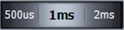
2.Horizontal [Time/Div]

Horizontal(X) axis coordinates system is designated as block time per scale. That is, if current Time/Div is set up as 1ms, the time that can be seen in the graph window is 1ms * 10 scales=10ms.
Time/Div is 22 values between 1us ~ 10s, and the value for each time unit is composed as below.
- us (9) : 1, 2, 5, 10, 20, 50, 100, 200, 500
- ms (9) : 1, 2, 5, 10, 20, 50, 100, 200, 500
- s (4) : 1, 2, 5, 10
The initial value is 1ms and if it is set up as over 50ms(total time 500ms), the graph is displayed as flowing by the time.
| Screen Area | Explanation |
|---|---|
 / /  |
left arrow: moves to the left of setup scale wheel (1ms => 2ms) right arrow: moves to the right of setup scale wheel (1ms => 500us) |
 |
Block time setup value. total 22 values us (9): 1, 2, 5, 10, 20, 50, 100, 200, 500 ms (9): 1, 2, 5, 10, 20, 50, 100, 200, 500 s (4): 1, 2, 5, 10 |
3.Vertical [Volt/Div]

Vertical Volt/Div setting can set up channel A and channel B separately and Volt/Div, ON/OFF, inversion(INV), coupling mode(AC/DC/GND) and Y-center reference axis movement are possible.
| Screen Area | Explanation |
|---|---|
 |
channel ON/OFF button |
 |
Channel graph inversion (graph is inverted based on X axis) |
 |
Channel Volt/Div setup. Sets up by the interval voltage per scale. maximum -50V ~ +50V can be set up. Interval Volt set up value (9 values) : 10V, 5V, 2V, 1V, 0.5V, 0.2V, 0.1V, 50mV, 20mV |
 |
Channel Y-Position movement. A, B channel center line reference position movement |
   |
Chooses the signal coupling mode. |
4.Trigger
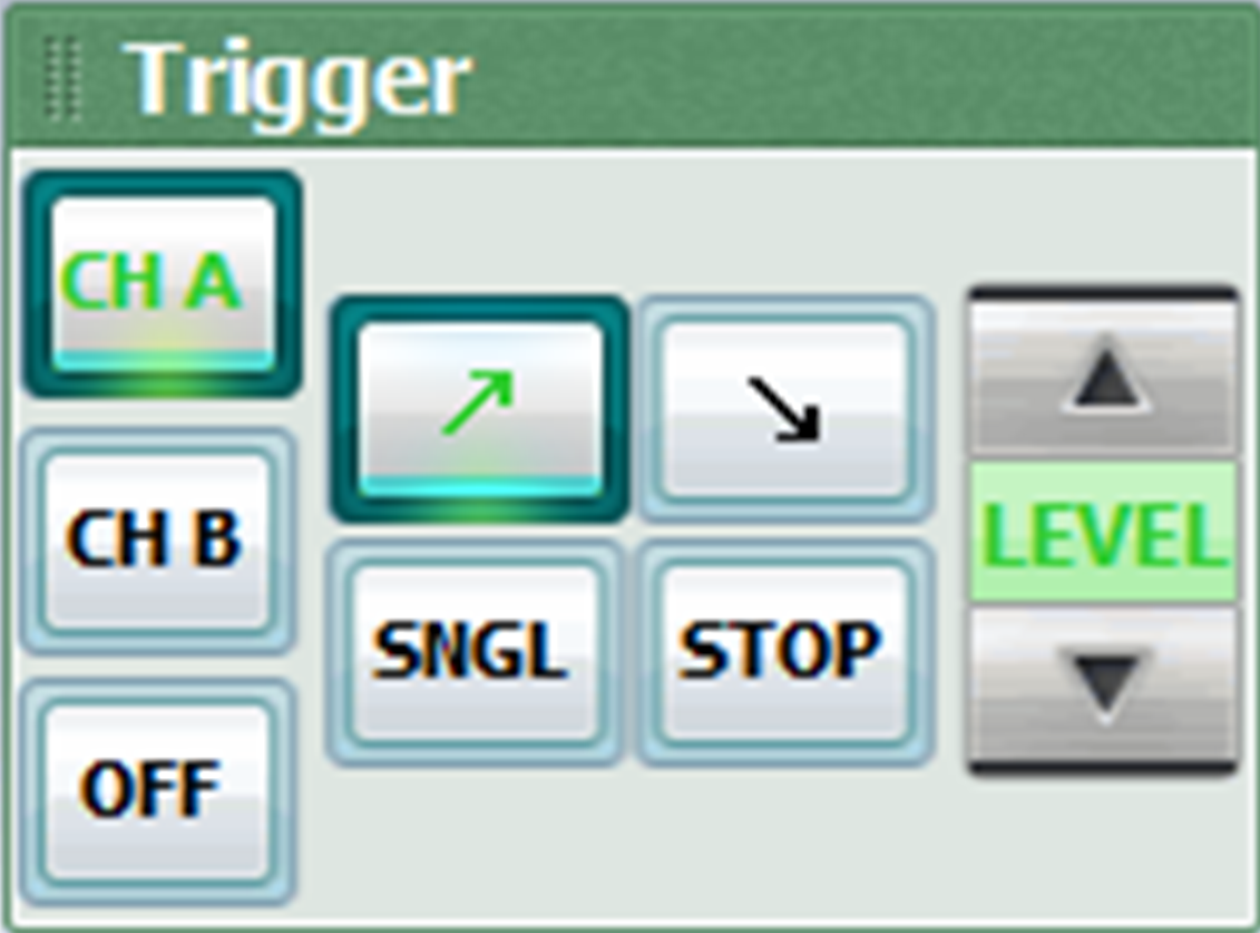
This is the function to set up the conditions of graph which will be generated by the trigger. There are trigger application channel, rising/falling edge, trigger critical value Y axis level, and the trigger can be stopped by SINGLE, STOP button according to the choice.
| Screen Area | Explanation |
|---|---|
   |
Channel choice button where the trigger is applied |
 |
Rising Edge: sets up the standard edge as when the value of voltage rises from the trigger critical value. Falling Edge: sets up the standard edge as when the value of voltage falls from the trigger critical value |
 |
(SINGLE) Outputs the result in the graph and stops after the measurement is finished with current trigger choice condition |
 |
Stops oscilloscope screen graph and the trigger |
 |
Y axis level value that judges the trigger’s edge. The initial value of trigger critical value setting is 0. |
2.Voltmeter & Ammeter
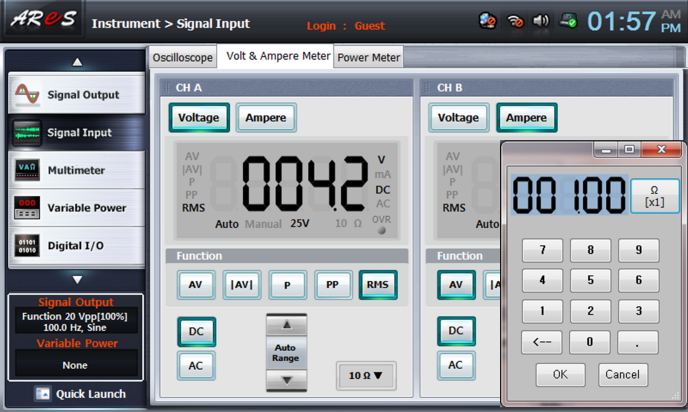
The measurement mode can be chosen and used so that voltage or current can be measured complexly in two channels. The current can be measured by virtual resistance input and if ammeter mode is chosen, the initial value of resistance is measured as 1Ω.
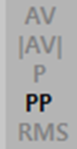
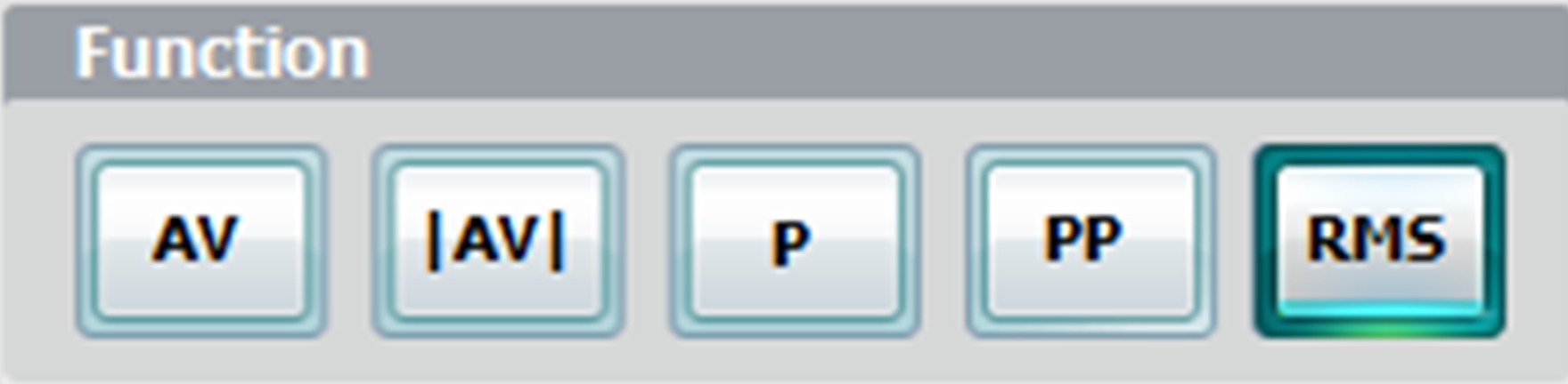
5 measurement modes, that is, AV, |AV|, P, PP, RMS are provided.
1.Voltage/Current Measurement Mode Choice per Channel
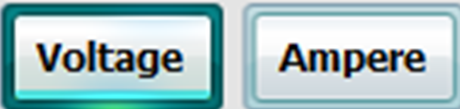
Here, you can choose voltmeter or ammeter measurement mode. You can choose the voltage or the current complexly for each channel.
| Screen Area | Explanation |
|---|---|
 |
Voltmeter mode activation button. The Range of information display window and the measurement unit on the right are displayed based on the voltage, and the resistance input button is deactivated. |
 |
Ammeter mode activation button. The Range of information display window and the measurement unit on the right are displayed based on the current, and the resistance input button is activated |
2.Voltage/Current Information Display Window
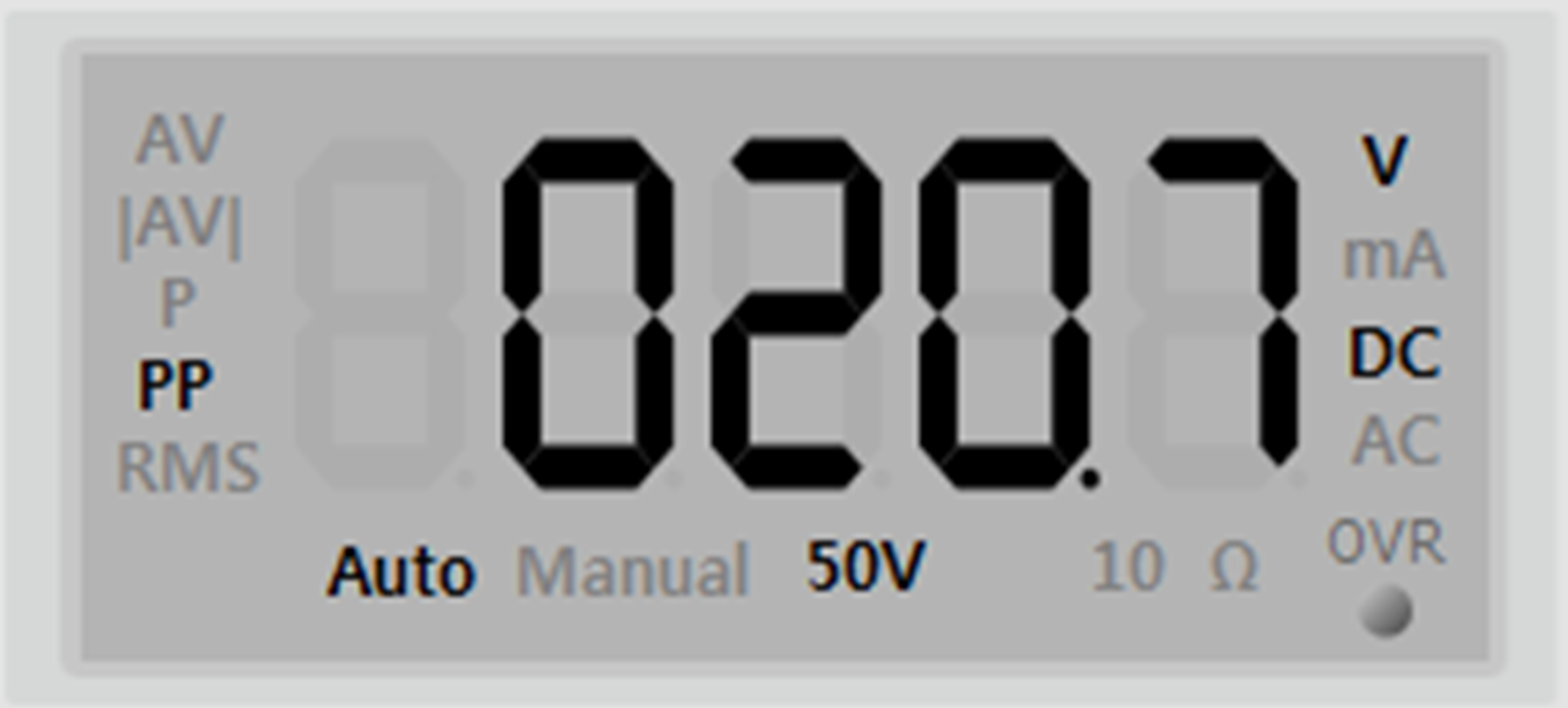
This is the voltage/current information display window. On the right is the measurement mode, on the bottom middle are Range status and resistance value, on the right is the measurement unit, on the very bottom is Over Range warning lamp.
| Screen Area | Explanation |
|---|---|
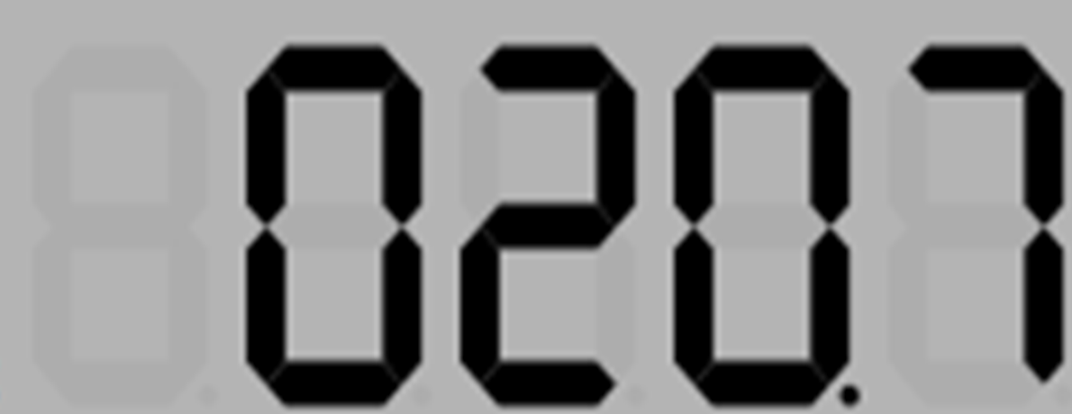 |
The measured value is displayed as digital at the center of the screen. |
 |
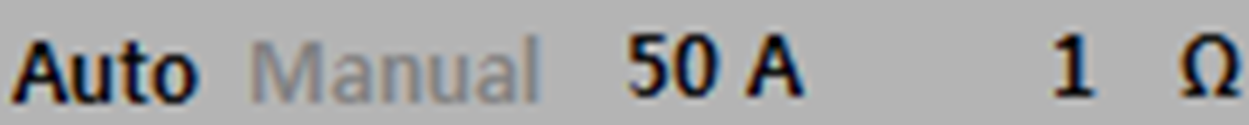
Activates the chosen measurement mode |
 |
Displays range value per Auto / Manual mode |
 / /  |
Red lamp flickers when the value exceeds(Over) the range. |
 |
Displays resistance value(activated when ammeter is used) |
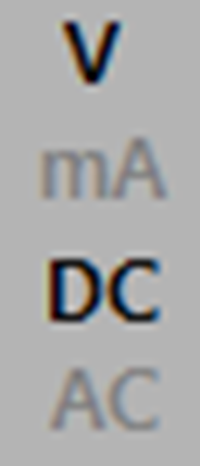 |
Displays voltage/current measurement unit and DC/AC coupling choice information |
3.Measurement Mode
The analog input information is measured by the measurement mode which was set up.
| Screen Area | Explanation |
|---|---|
 |
(Average Value) average value |
 |
(Average Value) absolute average value. |
 |
(Peak) maximum value. |
 |
(Peak to Peak) difference between maximum value and minimum value |
 |
(Root Mean Square) effective value |
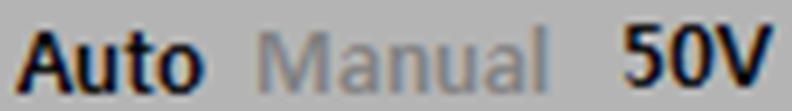
4.Measurement Option
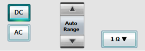
Here, DC/AC coupling and range can be chosen so that the measurement precision can be heightened. (Auto Range recommended)
| Screen Area | Explanation |
|---|---|
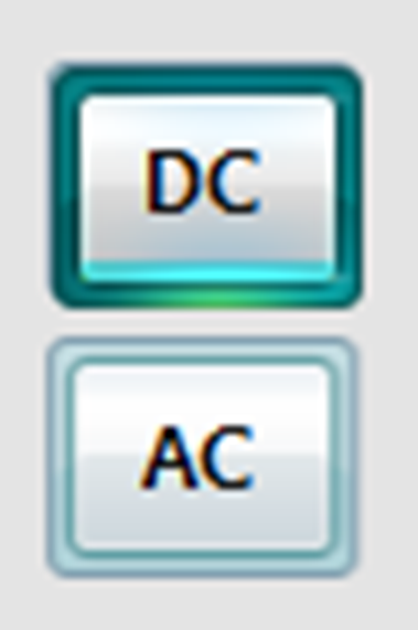 |
DC / AC coupling choice button. | 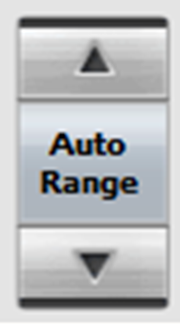 |
Range interval: total 9 values voltage: 100mV, 250mV, 500mV, 1V, 2.5V, 5V, 10V, 25V, 50V current: (voltage V/resistanceΩ) = current A. ex> 5V / 10Ω = 500mA Auto Range: the range interval optimal for the voltage value is set up automatically Manual: range is changed according to the user’s choice of up/down button |
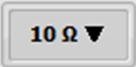 / / 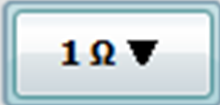 |
The button is activated only in ammeter mode and to change the value, choose the button and change the resistance value. Setup range of resistance value 0.01Ω ~ 1MΩ [initial value:1Ω] |
5.Resistance Input Window
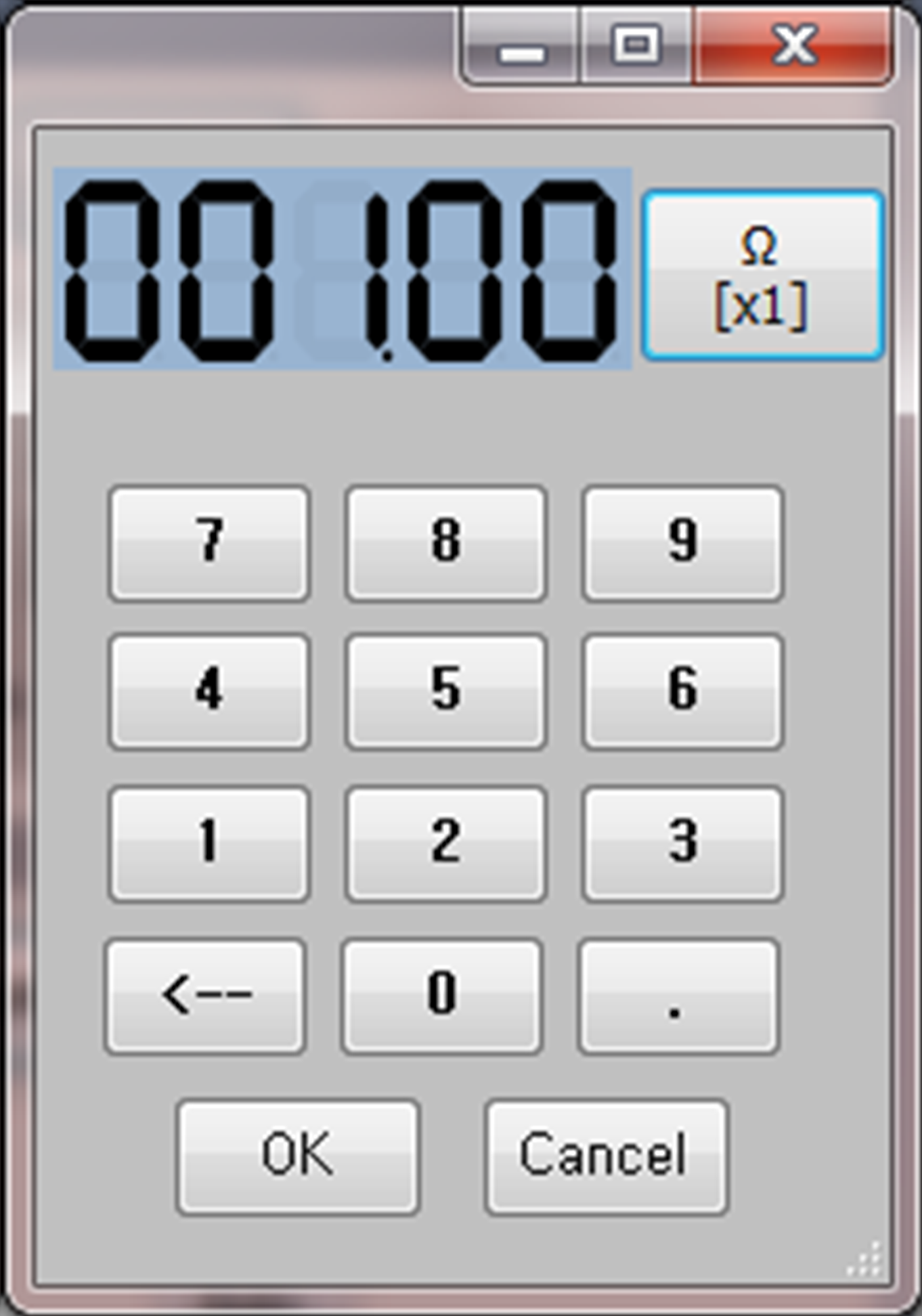
This is the input window for ammeter virtual resistance value. You can input the resistance value with number input keys and choose the resistance unit by unit change button and apply the resistance value.
| Screen Area | Explanation |
|---|---|
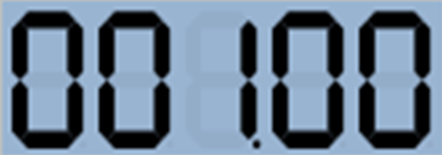 |
Resistance display window. Can input from two decimal places to three-digit number |
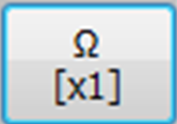 / / 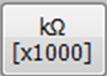 |
Unit change toggle key. The initial value is the current input resistance value(Ω) x1, and if it is clicked, the unit is changed to kΩ and it becomes as the input valuex1000. ex 1> 010.00 ( Ω[x1] ) = 10Ω ex 2> 010.00 (kΩ[x1000]) = 10kΩ |
 ~ ~  |
0 ~ 9 number input key. |
 |
Decimal point input key |
 |
Backspace key |
  |
OK button: closes the resistance input window and applies the input resistance value Cancel button: closes the resistance input window and maintains the input resistance value |
3.Wattmeter
The wattmeter calculates the energy(voltage*current) through the voltage that enters through CH A and the current of CH B. The resistance applied to the current can be adjusted by the user. If the range mode is set up as Auto Range, two channels, voltage and current, are automatically changed and in case of watt, the range is always automatically calculated and displayed on the screen.
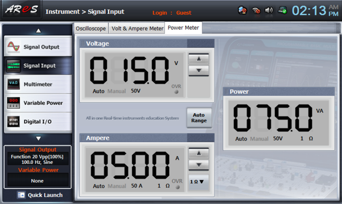
1.Voltage Display Window
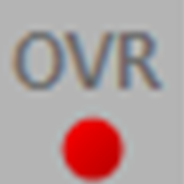
This window displays the voltage that is input to CH A according to the range setting. By manual adjusting button, the range can be set up as 9 values in 100㎷ ~ 50V, and if the measured voltage exceeds the range, OVR lamp flickers.
| Screen Area | Explanation |
|---|---|
 |
Displays input voltage of CH A |
|
Displays the setup range mode |
 / / |
Displays the measured voltage unit(㎷, V)If the value exceeds the range, OVR lamp flickers. |
 |
Manual range mode setup(total 9 values)voltage: 100㎷, 250㎷, 500㎷, 1V, 2.5V, 5V, 10V, 25V, 50V |
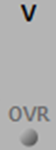
2.Current Display Window
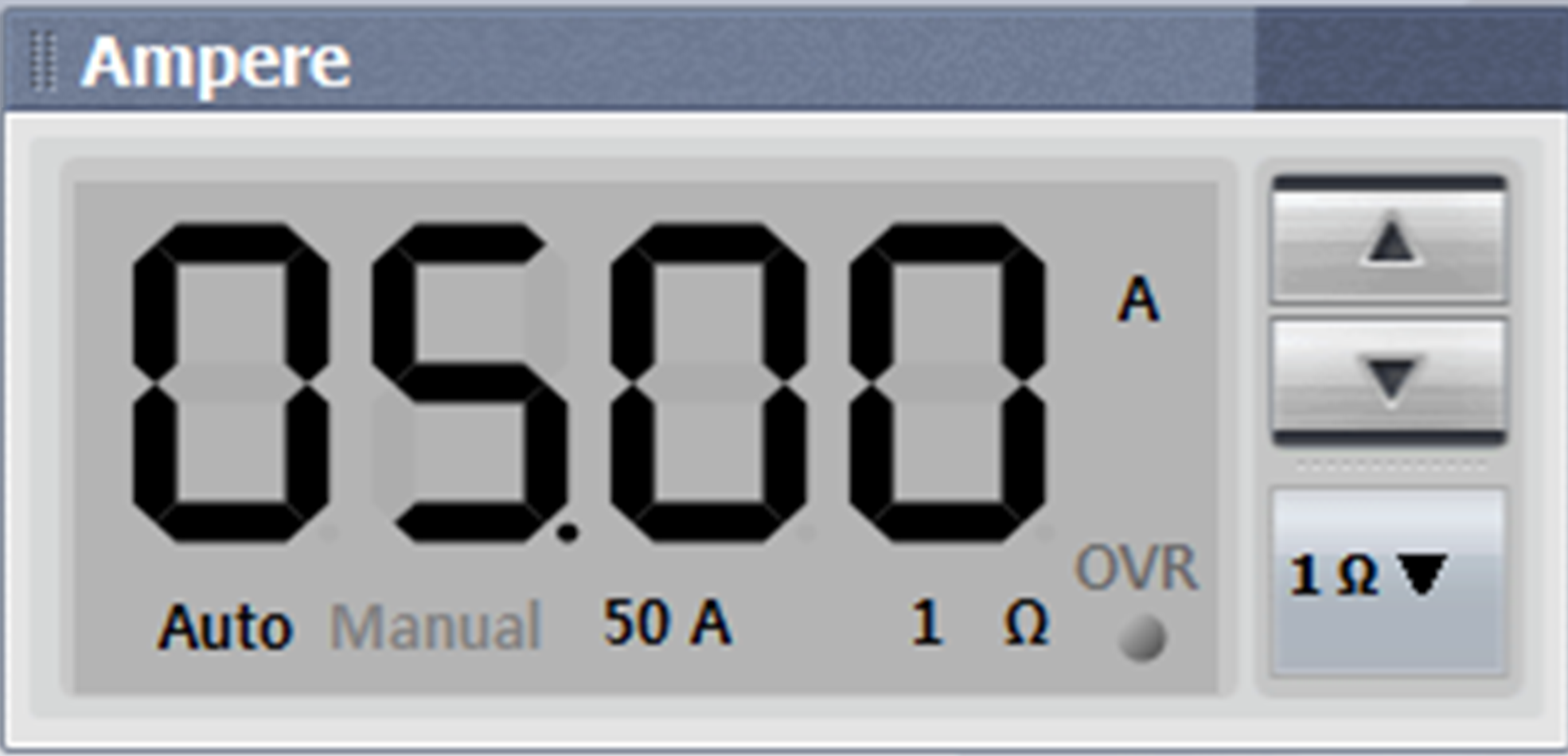
This window calculates the current with the voltage that is input to CH B based on the virtual resistance which is set up by the user and displays it on the screen according to the range setting. The range is the value that divides the voltage by the resistance and if the measured current exceeds the range, OVR lamp flickers.
| Screen Area | Explanation |
|---|---|
 |
Displays input current of CH A |
 |
Displays the range mode. The current range changes according to the setup resistance and the calculation formula is voltage/resistance. |
| / |
Displays the measured voltage unit(㎷, V)If the value exceeds the range, OVR lamp flickers. |
|
Manual range mode setup(total 9 values) current: 100㎃, 250㎃, 500㎃, 1A, 2.5A, 5A, 10A, 25A, 50A |
 |
Input resistance value display button. The value can be changed by click.* Refer to Ammeter Resistance Input Window. |
3.Watt Display Window
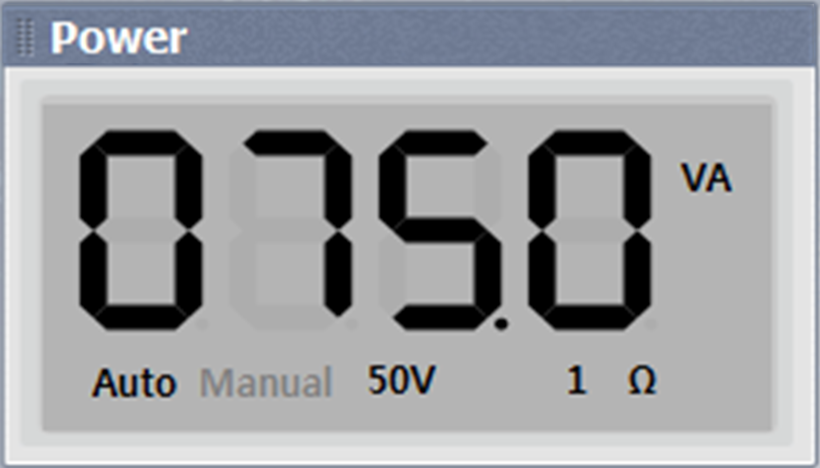
The multiplication of CH A(voltage) and CH B(current) is displayed as watt and the range is displayed by being calculated as Auto Range. (watt = voltage * current)
| Screen Area | Explanation |
|---|---|
 |
Displays the multiplied value between CH A(voltage) and CH B(current), that is, watt, on the screen. watt(VA) = voltage(V) * current(A) |
|
The range is displayed as Auto mode. Basically, it is displayed in the form that is displayed in the range mode of voltage. |
 |
Displays the watt unit.(voltage V * current A = VA) |
4.Auto Range
In the wattmeter, the auto range does not exist separately to voltage and current. When the range of one among the two is auto, all of them are operated as auto range.
| Screen Area | Explanation |
|---|---|
 |
Changes the range mode to auto |