PART8Operating Amplifier Circuit(OP AMP)
Experiment 5 :Summing Amplifier
Theory
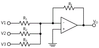
As in fig. 8-11, if multiple input resistances are connected to inverting input (-) terminal of OP-Amp at the same time, it becomes adder. Multiple input voltages are combined in this circuit so the output voltage becomes as below.
![V_o=-[R_f/R1 V1+R_f/R2 V2+R_f/R3 V3]=-R_f [V1/R1+V2/R2+V3/R3]](../image/part8/formal8.20.gif)
Except that this has multiple inputs, this is same as inverting amplifier. If the feedback resistance Rf and input resistance R1, R2, R3 are all same, it becomes as below.

Meanwhile, if the value of feedback resistance is bigger than 3 same input resistances, it is composed as a circuit that has gain. The input impedance for each input is determined by the value of corresponding input resistance.
Another useful circuit composition is the average that calculates the average of voltage. By choosing proper ratio of feedback to same input resistance, it can be the average value of total input resistance. For example, in the circuit of fig. 8-10, the average of three inputs becomes as below.

If R1=R2=R3=R f /3, the average of these three input signals can be calculated.
Experiment Process
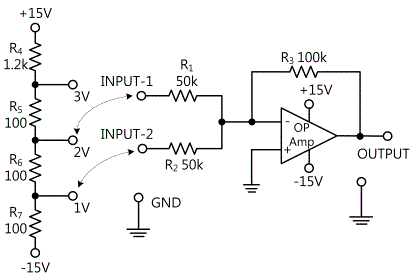
> tab1Experiment 8-5.1 Summing amplifier experiment (Circuit-6 of the M08 consists of the circuit in Fig 8-12)
1.Connection(Circuit-5 of M-08)
1.Power Connection
It is connected internally.
2.Measuring Instrument Connection
Variable Power Connection
Connect between V1 terminal of Variable Power on front panel and 6f terminal of Circuit-6 with red line and between COM terminal and 6c terminal with black line.(Wiring diagram. Through 2 step)
Multimeter Connection
Connect between High terminal of Multimeter on front panel and 6d terminal of Circuit-6 with red line, and between Low terminal and 6e terminal with black line.(Wiring diagram. Through 4 step)
2.Wiring Diagram
3.Measurement
- 1Click variable power at Touch LCD panel and choose 3CH DC.
Click and set up V1 as 15V and click and output DC to Circuit-6.
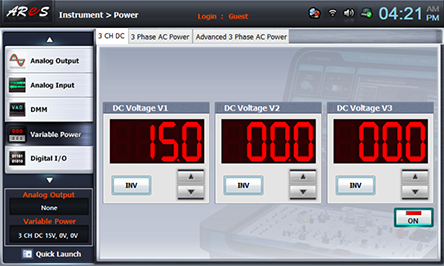
- 2Apply 2V to Input-1, and 1V to Input-2 and measure output voltage.
For Input-1, connect between 6a terminal and 6h terminal with red line, and for Input-2, connect between 6b terminal and 6i terminal with red line. (The earthing is connected internally.)(Wiring diagram. Through 6 step)
Click dmm at Touch LCD panel, choose and record the measured value in the relevant column of table 8-8.
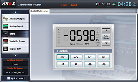
- 3Apply 3V to Input-1, and 1V to Input-2 and measure output voltage.
For Input-1, connect between 6a terminal and 6g terminal with red line, and for Input-2, connect between 6b terminal and 6i terminal with red line. (The earthing is connected internally.) Record the measured value in the relevant column of table 8-8.(Wiring diagram. Through 7 step)
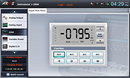
After the measurement, choose varaible power and click to cut off the output.
- 4Apply 3V to Input-1, and -5V to Input-2 and measure output voltage.
For Input-2, change the connection between 6b terminal and 6i terminal to the connection between 6b and V2 terminal of Variable Power on front panel.(Wiring diagram. Through 8 step)
Click dmm at Touch LCD panel, choose quick launch at the left bottom of Touch LCD panel, click Variable Power and use of DC Voltage V2 at 3CH DC and adjust as V2(Input-2)=5V, and click to make -5V and click and record the measured value of DMM in the relevant column of table 8-8.
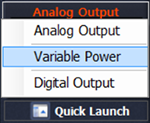
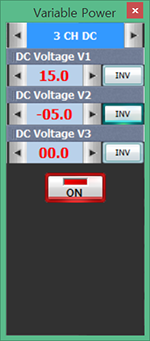
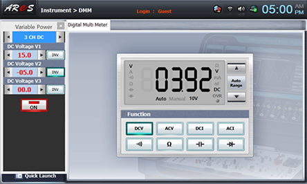
After the measurement, click to cut off the output.
- 5Apply -5V to Input-1, and +5V to Input-2 and measure output voltage.
For Input-1, change the connection between 6a terminal and 6g terminal to the connection between 6a and 6f terminal.(Wiring diagram. Through 9 step)
In the left quick launch screen, adjust asV1(Input-1)=5V using DC Voltage V1 and click to make -5V, and click again to make -5V of DC Voltage V@ as +5V, and click and record the measured value of DMM in the relevant column of table 8-8.
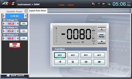
After the measurement, click to cut off the output.
4.Calculation
1. Using the formula below, calculate the output voltage with the input measured value of table 8-8 and record it in the relevant column of table 8-8.
![V_o=-[R_f/R1 V1+R_f/R2 V2+R_f/R3 V3]=-R_f [V1/R1+V2/R2+V3/R3]](../image/part8/c5.gif)
Experiment Result Report
1. Experiment Result Table
2. Review and Explanation
1) In table 8-8, calculate the output voltage using the formula below.
Calculate by referring to the resistance R1, R2, R3~R8 in Circuit-6.

![V_o=-[R_f/R1 V1+R_f/R2 V2+R_f/R3 V3]=-R_f [V1/R1+V2/R2+V3/R3]](../image/part8/c5.gif)


