


PART12Pulse Circuit
EXperiment 3 :Bistable Multivibrator Circuit
Theory
Bistable multivibrator is also called filp-flop circuit, and this circuit is used as divided frequency circuit, scaling circuit and information memory circuit. As in fig.12-13, this is composing the connection of each translator of non-stable multivibrator by resistance division. Therefore, in stable state, Tr1 is ON and Tr2 is OFF, or Tr1 is OFF and Tr2 is ON. When Tr1 is ON and Tr2 is OFF, the collector of Tr1 is 0V, so (-) voltage is applied to the base of Tr2 by VBB so Tr2 is OFF, and Tr1 is ON, which is a stable state. When (+ voltage is applied to the trigger input, CT1 is charged because Tr1 is ON and 0V, but CT2 is not charged because Tr2 is OFF high potential is applied at one side. In this state, if the trigger voltage suddenly falls to 0V, the electric potential of CT1 is reversely applied to between base-emitter of Tr1 by the diode and makes Tr1 OFF, and affected by this, the state of Tr2 is reversed as ON. This operation occurs again when the trigger input suddenly falls from 0V to (-) voltage. Like this, the state of flip-flop circuit is reversed when the trigger voltage falls, so when 2 pulses enter, 1 pulse comes from the collector of Tr1 or, Tr2 and it is operated as a divided frequency or scaling circuit.
When the trigger input is divided as Tr1 side and Tr2 side and if the trigger is applied, one trigger path can be reduced as Set state, and the other as Reset state. This is called R-S Flip-Flop and is used for information memory.
Experiment Process
1. In Circuit-3 of M-12, connect between 3j-3k, and between 3l-3m terminals to compose a circuit as in fig.12-14.
2. Press the switches as the order in table 12-4, measure the states of LED-1, LED-2, and OUT-1 and OUT-2 and indicate O to the relevant columns.
3. As in fig.12-14, input 100Hz, 1000Hz square waves to 3a-3b terminals, measure the output frequency and output period for each case and compare the result to the input period. Indicate the measured result in the table.
tab1Experiment 12-3.1 Bistable Multivibrator Circuit Experiment (In Circuit-3 of M12, compose a circuit as in fig.12-14.)
1.Connection
1.Circuit Connection
In Circuit-3 of M12, Connect between 3j-3k terminal, and between 3l-3m terminal with yellow lines.
2.Power connection is internally connected.
3.Measuring Instrument Connection
Oscilloscope and Voltmeter Connections
Output-1 Voltage Measurement Connection: Connect between 3a terminal of Circuit-3 and A+ terminal of Signal Input CH A on the front panel with red line, and between 3b terminal and A- terminal with black line.
Output-2 Voltage Measurement Connection: Connect between 3i terminal of Circuit-3 and B+ terminal of Signal Input CH B on the front panel with red line, and between 3n terminal and B- terminal with black line.
2.Wiring Diagram
flash
3.Measurement
- 1In Circuit-3 of M12, compose a circuit as in fig.12-13.
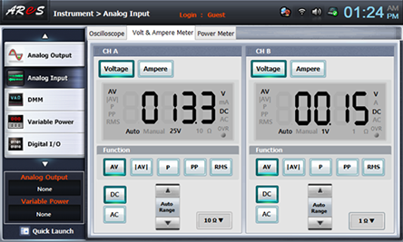
- 2Click analog input at front panel, choose Volt & Ampere Meter tab, click , , at CH A, B, and measure as High when the indicated output voltage is over 13V, and as Low when it is under 1V.
(CH A = Output 1, CH B = Output -2) - 3Press the switches as the order in table 12-4, measure the states of LED-1, LED-2, and OUT-1 and OUT-2 and indicate O to the relevant columns.
10Vpp :
- 4As in fig.12-14, input 100Hz, 1000Hz square waves to 3o-3p terminals, measure the output frequency and output period for each case and compare the result to the input period. Indicate the measured result in the table.
Circuit Connection
In Circuit-3 of M12, Connect between 3j-3k terminal, and between 3l-3m terminal with yellow lines.
Plug in BNC cable to BNC terminal of Signal Output on front panel and connect red line to 3p terminal of Circuit-3, and black line to 3o terminal.
Oscilloscope and Voltmeter Connection
Input Voltage Measurement Connection: Connect between 3p terminal of Circuit-3 and A+ terminal of Signal Input CH A on the front panel with red line, and between 3q terminal and A- terminal with black line.
Output-1 Voltage Measurement Connection: Connect between 3a terminal of Circuit-3 and B+ terminal of Signal Input CH B on the front panel with red line, and between 3b terminal and B- terminal with black line.
Wiring Diagram
flash
Measurement
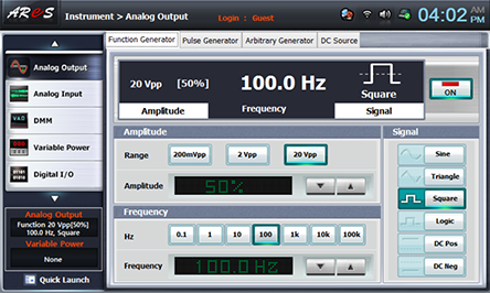
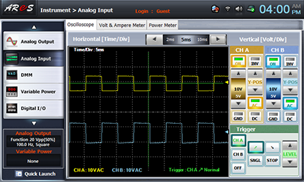
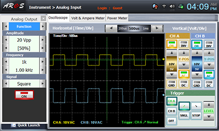
Choose analog output at Touch LCD panel, set up Amplitude Range as , and Amplitude as amplitude 50% . Choose at Frequency to make 1hkz. Set up Signal as , and click to send the output to Circuit-3.
Choose analog input at front panel and draw the wave form in oscilloscope screen in the relevant column of table 12-5
- 5After the measurement, click at quick launch screen and cut off the output.