


PART10Power Supply Circuit
Experiment 3 :Variable Voltage Regulator
tab1
Experiment 10-3.1
Variable Constant Voltage Circuit Experiment Using Transistor
(In Circuit-1, 2 , 3 of M10, compose a variable constant voltage circuit by transistor as in fig 10-13.)
1.Connection(Circuit -1,2,3 of M-10)
1.Circuit Connection
Capacitor C1, C2 Connection; Connect between 1g terminal and 1k terminal , between 1h terminal and 1l terminal of Circuit-1 with yellow line.(Wiring diagram. Through 2 step)
Variable Constant Voltage Circuit; Connect between 1j terminal of Circuit-1 and 3a terminal of Circuit-3 with red line, and between 1n terminal and 3b terminal of Circuit-2 with black line.(Wiring diagram. Through 4 step)
2.Power Connection
Connect between Variable Power V1 terminal on the left of M10 board and 1a terminal of Circuit-1 with red line, and between COM terminal and 1b terminal with black line.(Wiring diagram. Through 6 step)
3.Measuring Instrument Connection
Voltmeter Connection
Input Voltage Measurement Connection(Input Voltage): Connect between 3k terminal of Circuit-3 and A+ terminal of Signal Input CH A on the front panel of Multimeter with red line, and between 3l terminal and A- terminal with black line.(Wiring diagram. Through 8 step)
Input Voltage Measurement Connection(Ripple Effective Voltage): Connect between 3k terminal of Circuit-3 and B+ terminal of Signal Input CH A on the front panel of Multimeter with red line, and between 3l terminal and B- terminal with black line.(Wiring diagram. Through 10 step)
2.Wiring Diagram
flash
3.Measurement
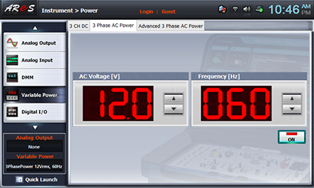
- 1Choose variable_power at Touch LCD panel, and click 3 Phase AC Range Power tab.
Click at the right of AC Voltage indication window and make it as 12.0V.
Click and apply the output of 3 Phase AC Range Power to the input of Circuit-1.
- 2Measure the output ripple effective voltage and ripple rate with no-load when setting the output voltage as 6V.
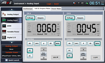
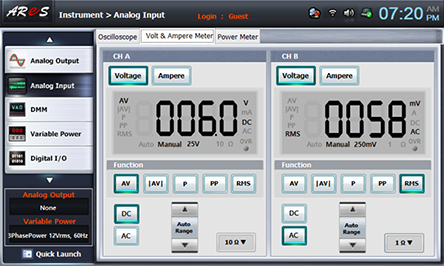
Choose analog input at the front panel, choose Volt & Ampere Meter tab and click , , at CH A, and , , at CH B.
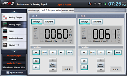
Adjust the variable resistance R4 for output voltage adjustment, and make the voltage of CH A as 6V, then record the ripple effective output voltage measured in CH B in the relevant column of table 10-5.
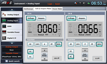
- 3Measure the output ripple maximum voltage, effective voltage and ripple rate when the output voltage is set up as 6V.
120Ω Load Connection: Connect between 2j terminal of Circuit-2 and 3k terminal of Circuit-3 with red line, and between 2l terminal and 3l terminal with black line.(Wiring diagram. Through 12 step)
Adjust the variable resistance R4 for output voltage adjustment, and make the voltage of CH A as 6V, then record the ripple effective output voltage measured in CH B in the relevant column of table 10-5.
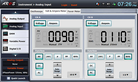
- 4Measure the output ripple effective voltage and ripple rate with load and with no-load when changing the output voltage as 7.5V and 9V.
Execute the measurement process 2) 3) and record the measured value in the relevant column of table 10-5.


After the measurement, choose variable power and click to cut off AC 12V output.
Experiment 10-3.2
Variable Constant Voltage Circuit Experiment Using OP-Amp
(Using Circuit-1, 2, 4 of M10, compose a variable constant voltage circuit
by OP-Amp as in fig 10-14.)
1.Connection(Circuit -1,2,4 of M-10)
1.Circuit Connection
Capacitor C1, C2 Connection; Connect between 1g terminal and 1k terminal , between 1h terminal and 1l terminal of Circuit-1 with yellow line.(Wiring diagram. Through 2 step)
Variable Constant Voltage Circuit; Connect between 1j terminal of Circuit-1 and 4a terminal of Circuit-4 with red line, and between 1n terminal and 4b terminal of Circuit-2 with black line.(Wiring diagram. Through 4 step)
2.Power Connection
Connect between Variable Power V1 terminal on the left of M10 board and 1a terminal of Circuit-1 with red line, and between COM terminal and 1b terminal with black line.(Wiring diagram. Through 6 step)
3.Measuring Instrument Connection
Voltmeter Connection
Input Voltage Measurement Connection(Input Voltage): Connect between 4i terminal of Circuit-4 and A+ terminal of Signal Input CH A on the front panel of Multimeter with red line, and between 4j terminal and A- terminal with black line.(Wiring diagram. Through 8 step)
Input Voltage Measurement Connection(Ripple Effective Voltage): Connect between 4i terminal of Circuit-4 and B+ terminal of Signal Input CH A on the front panel of Multimeter with red line, and between 4j terminal and B- terminal with black line.(Wiring diagram. Through 10 step)
2.Wiring Diagram
flash
3.Measurement
- 1Execute 1), 2), 3), 4) of [Variable Constant Voltage Circuit using Transistor, Fig. 10-13 Circuit]>3. Measurement and record it in the relevant column of table 10-5.
How to connect 120Ω load: Connect between 2j terminal of Circuit-2 and 4i terminal of Circuit-4 with red line, and between 2l terminal and 4j terminal with black line.

4.Calculation
1. Calculate the ripple rate by the formula below.
![Ripple Rate= (Ripple Voltage (V_rms))/(DC Output Voltage (V_AV))×100[%]](../image/part10/c12.gif)